(German Version)
(last updated:
April 03, 2024)
After spending a decent amount of time searching the
internet to figure how to control a Märklin digital model Railroad without Central Station 2 (CS2)
using a PC and Rocrail, I have decided to create this page to save you some
time.
Quick Jump:
New:
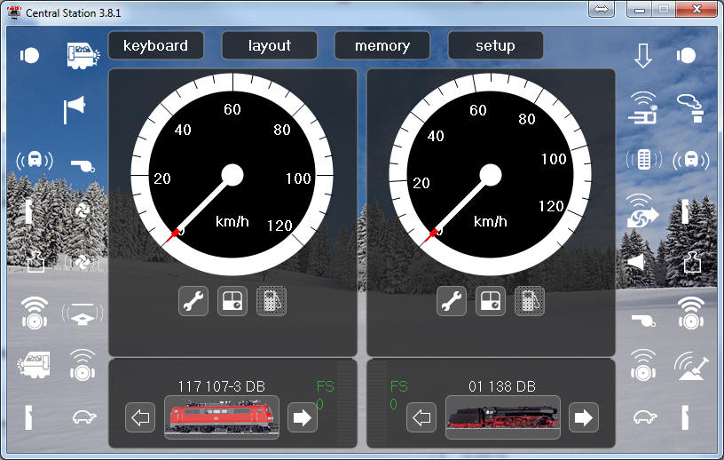
Using the free Märklin Software:
Central Station v 3.8.1
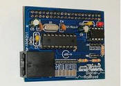
A dutch guy has created an own board design, and has has 10 boards
left which he is selling now, with or without parts.
His prices:
only PCB 10.- €
PCB + components 27.50 €
PCB fully assembled: 47.50 €
If you are interested, you can write an email to this guy: ledje@telfort.nl
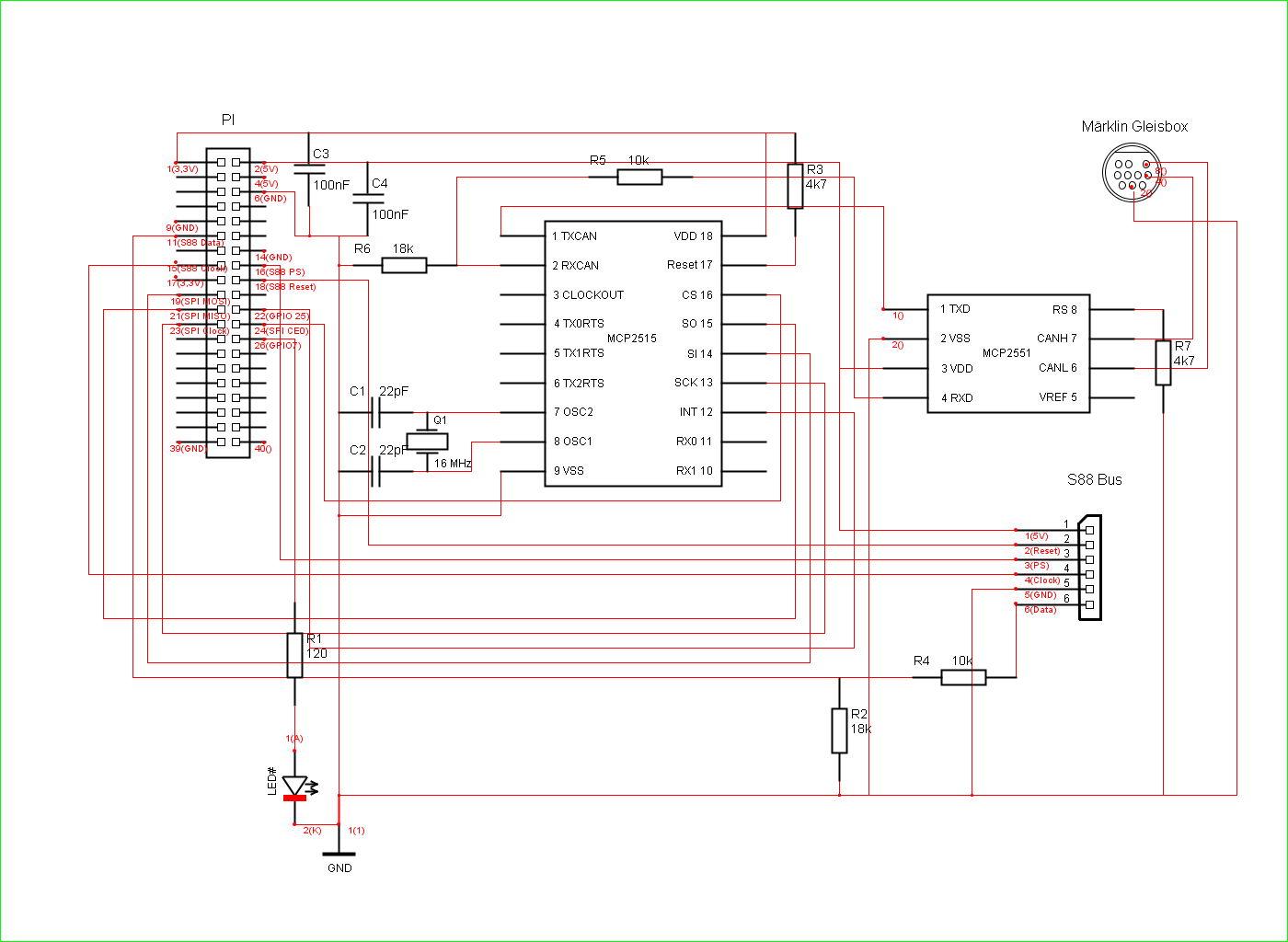
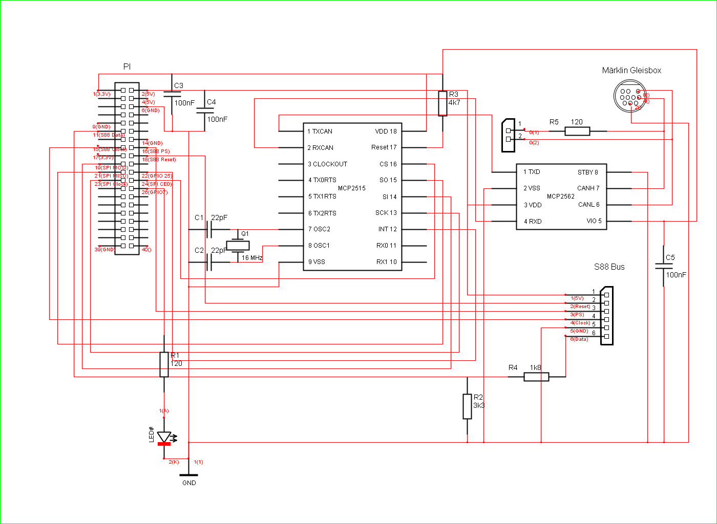
Circuit diagram for the CAN -
Bus access including S88 Feedback channel V1:
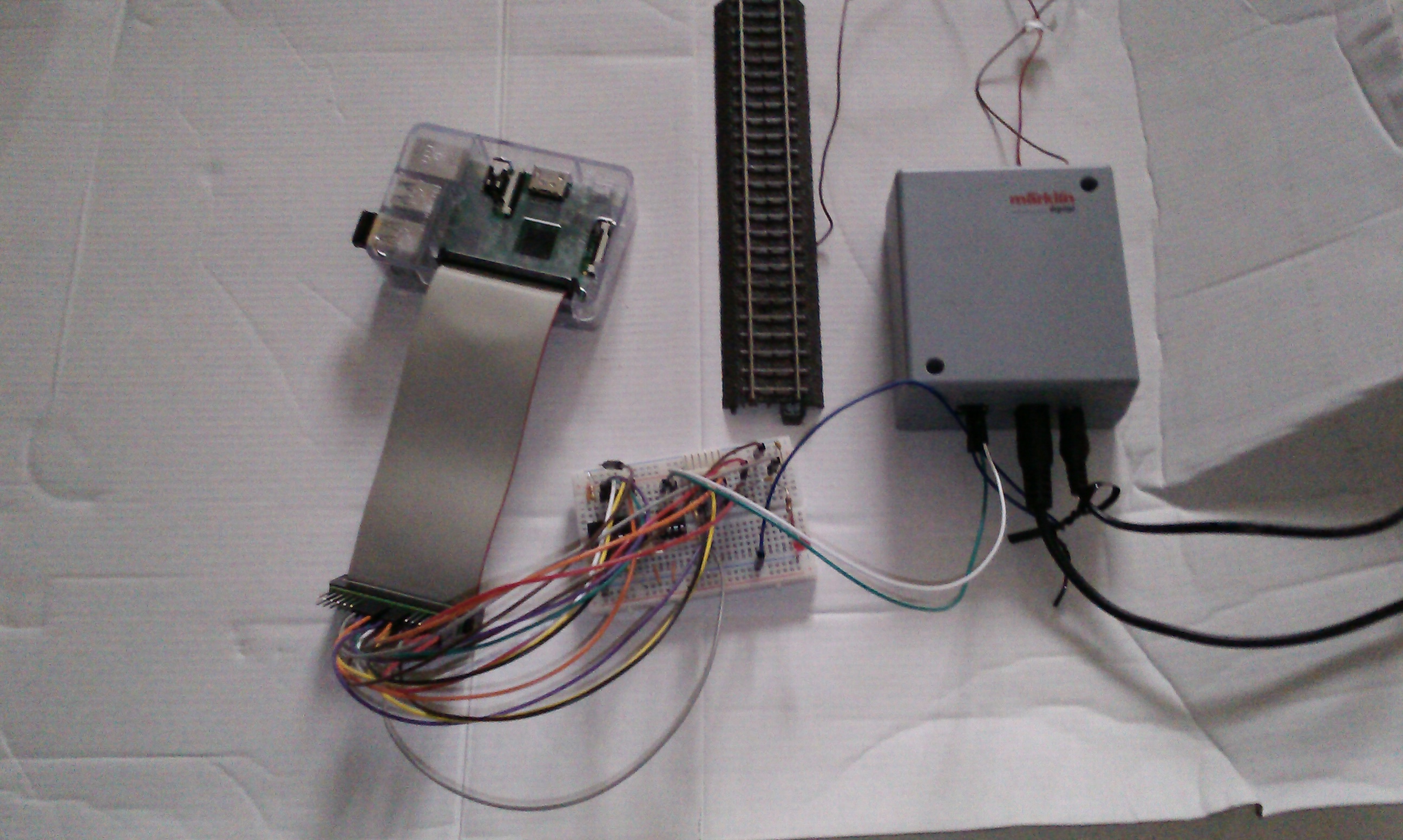
The key for controlling using a Raspi, is the Märklin
Gleisbox, which offers a CAN Interface, which we can use.
Before we can use a CAN Interface with a Raspi, we need an
additional circuit diagram using 2 CAN - Bus controller chips, the MCP2515 and
MCP2551.
I did build this circuit diagram on a breadboard, so no soldering is required.
After it was working perfectly, I have decided to create a circuit board which
fits into the Raspberry PI. So here is now my Step by Step instruction for you:
Components Parts List:
| Komponent |
Value |
Amount |
Part |
Order Nr. |
|
Keramik Capacitor
|
0,1 uF / 100 nF |
2 |
C3, C4 |
Bürklin Nr.: 53D3648 |
|
Keramik
Capacitor
|
22 pF |
2 |
C1, C2 |
Bürklin Nr.: 53D3004 |
|
Miniatur Quarz |
16 Mhz |
1 |
Q1 |
Bürklin Nr.: 78D154 |
|
IC MCP2551 |
MCP2551 |
1 |
MCP2551 |
Bürklin Nr.: 64S2272 |
|
IC MCP2515 |
MCP2515 |
1 |
MCP2515 |
Bürklin Nr.: 64S2268 |
|
Resistor |
18 kOhm |
2 |
R2, R6 |
Bürklin Nr.: 17E325 |
|
Resistor |
10 kOhm |
2 |
R4, R5 |
Bürklin Nr.:
17E310 |
|
Resistor |
4,7 kOhm |
2 |
R3, R7 |
Bürklin Nr.:
17E280 |
|
Resistor |
120 Ohm |
1 |
R1 |
Bürklin Nr.:
17E175 |
|
Stiftleiste gebogen |
3 polig |
3 |
|
Bürklin Nr.:
59F2268 |
|
LED 5 mm |
Rot |
1 |
LED |
Bürklin Nr.: 67S4500 |
You can order these components at this German supplier:
https://www.buerklin.com/default.asp?l=e
Circuit diagram for the CAN -
Bus access including S88 Feedback channel Version 2:
This new version is using the new MCP2562 instead of the old MCP2551.
Advantage is, this new chip can use 3.3V as reference, and doesn't need voltage
dividers, and it's said to be more stable.
In addition I am using for the S88 feedback as voltage
dividers the new resistor values 1,8k and 3,3k, which are giving a better
division ratio as in V1.
An optional Terminating-Resistor for the CAN Bus with 120 Ohm
is now also added which can be "jumpered" if needed.
A guide how to solder the empty PCB with the new V2 circuit diagram can be found
here.
Components Parts List V2:
| Komponent |
Value |
Amount |
Part |
Order Nr. |
|
Keramik Capacitor
|
0,1 uF / 100 nF |
3 |
C3, C4, C5 |
Bürklin Nr.: 53D3648 |
|
Keramik
Capacitor
|
22 pF |
2 |
C1, C2 |
Bürklin Nr.: 53D3004 |
|
Miniatur Quarz |
16 Mhz |
1 |
Q1 |
Bürklin Nr.: 78D154 |
|
IC MCP2562 |
MCP2562 |
1 |
MCP2562 |
Bürklin Nr.: 64S2272 |
|
IC MCP2515 |
MCP2515 |
1 |
MCP2515 |
Bürklin Nr.: 64S2268 |
|
Resistor |
1,8 kOhm |
1 |
R4 |
|
|
Resistor |
3,3 kOhm |
1 |
R2 |
|
|
Resistor |
4,7 kOhm |
1 |
R3 |
Bürklin Nr.:
17E280 |
|
Resistor |
120 Ohm |
1 |
R1 |
Bürklin Nr.:
17E175 |
|
Stiftleiste gebogen |
3 polig |
3 |
|
Bürklin Nr.:
59F2268 |
|
LED 5 mm |
Rot |
1 |
LED |
Bürklin Nr.: 67S4500 |
|
|
|
|
|
Reichelt_Basket |
Alternative Circuit diagram like Version 2:
Heiko Thiery created an own circuit diagram like my version 2,
which might be useful to you, and made it
public on
GitHub here as PDF document.
In his plan he is also using an Optocuppler for the S88 feedback, which protects
the Pi additionally.
Many greetings and thanx to Heiko Thiery.
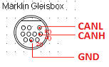
The proper Din
10 Miniatur Connector for the Märklin Gleisbox can be obtained by Email
request from this person:
info@can-digital-bahn.com
Useful parts at Conrad.de:
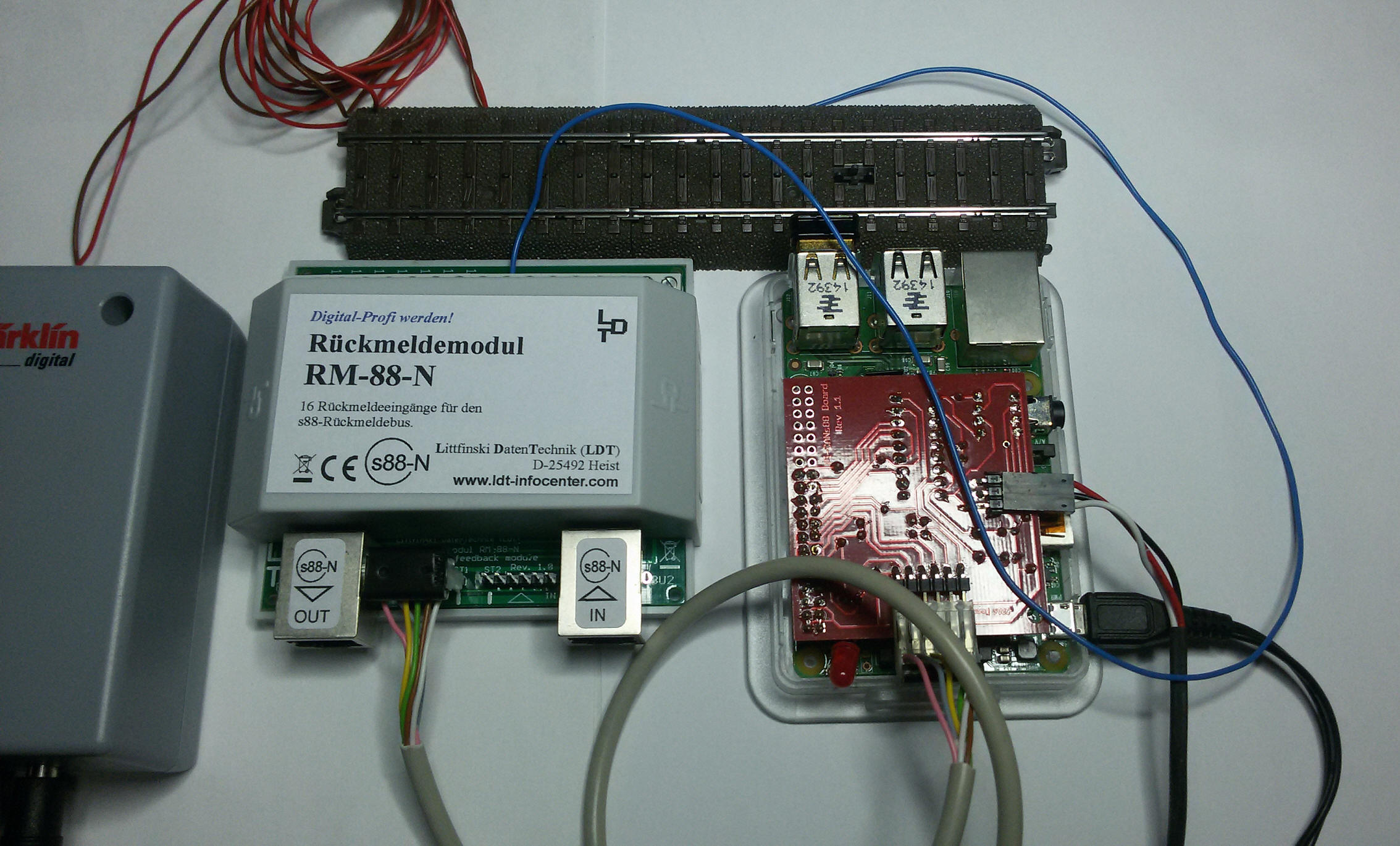
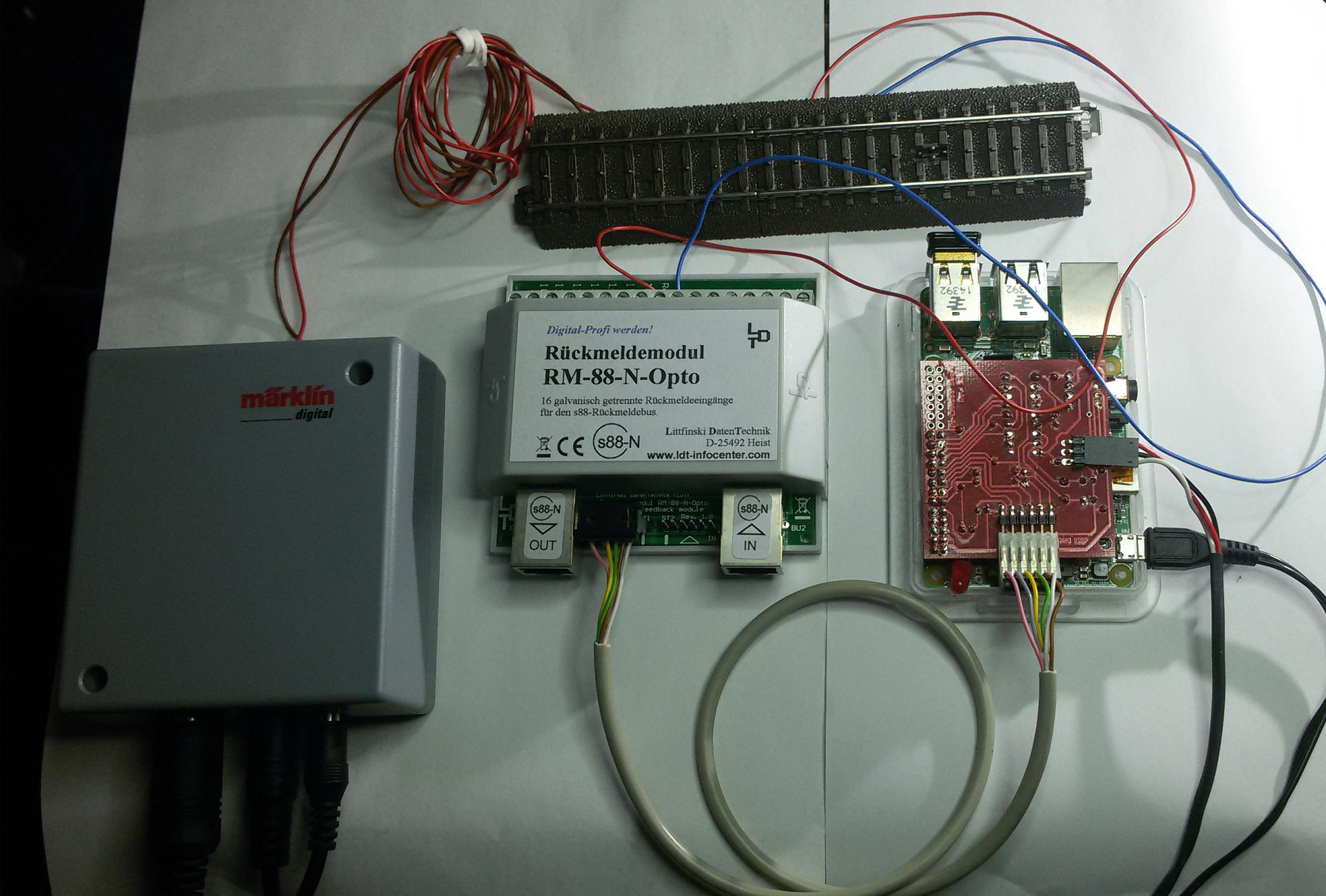
Recommended Feedback Module
with galvanic isolation:
For beginners and for your first testing purposes, I suggest
to use above S88 feedback module from Littfinski Daten Technik (LDT), because it
is using a galvanic isolation between the railroad track and the central
station/Pi.
Using regular modules could cause a damage of your central station/Pi if you do
incorrect wiring.
Useful parts at company: tams:
Attention:
Using above tams S88-N Adapters can be dangerous, because of reverse
voltage connection.
For proper usage please read this part, and if you still
have doubts, ask me by email.
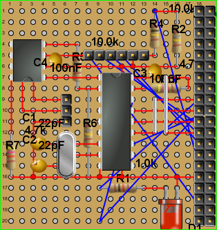
Mounting the circuits on a Breadboard:
All following mounting instructions are based on circuit
diagram Version 1 !
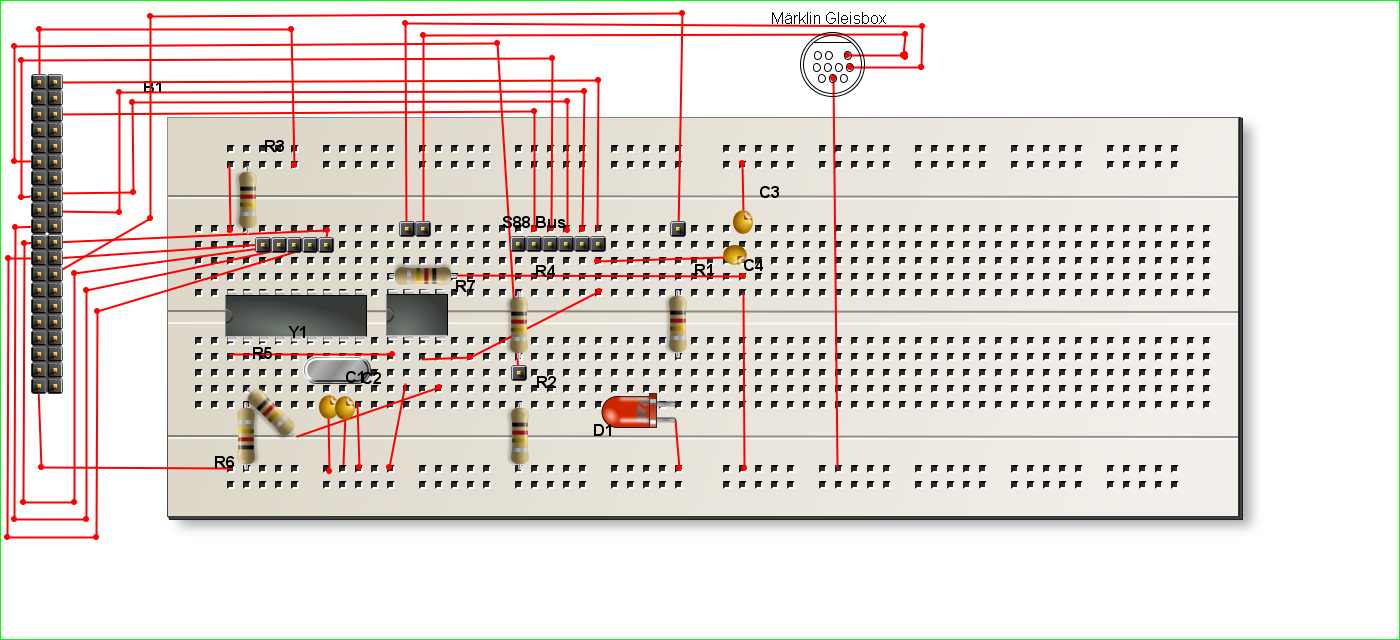
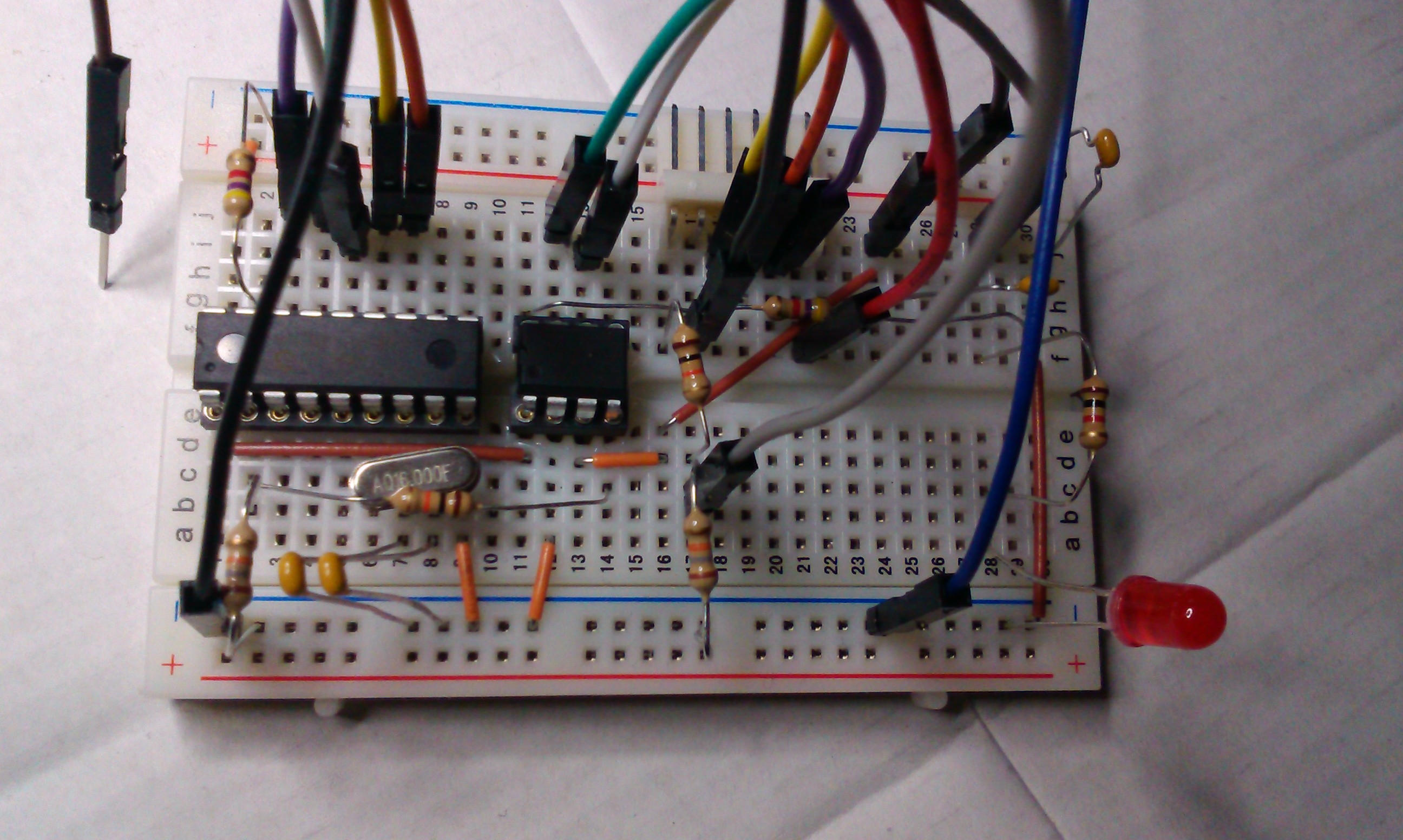
Live picture:
Attention!
In above mounting instruction, the order of the S88 feedback
pins is opposite, because I couldn't get a real S88-connector. So a real S88
Module has to be connected to this example upside-down as you can see in below
picture:
A complete connection example:
Attention: If the connections CAN High and CAN Low are
switched, the Chip MCP2551 gets very hot and can get destroyed. So if you
connect this example for the first time, hold your finger on the chip to check
its temperature, and if it gets hot, cut the power supply imediatly.
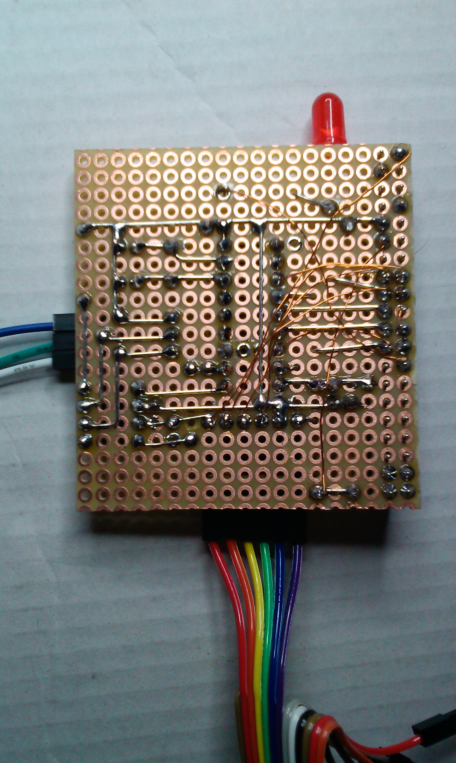
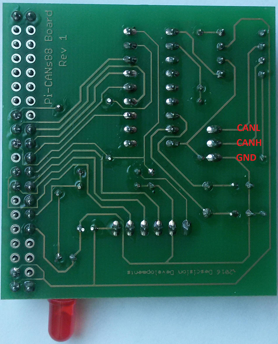
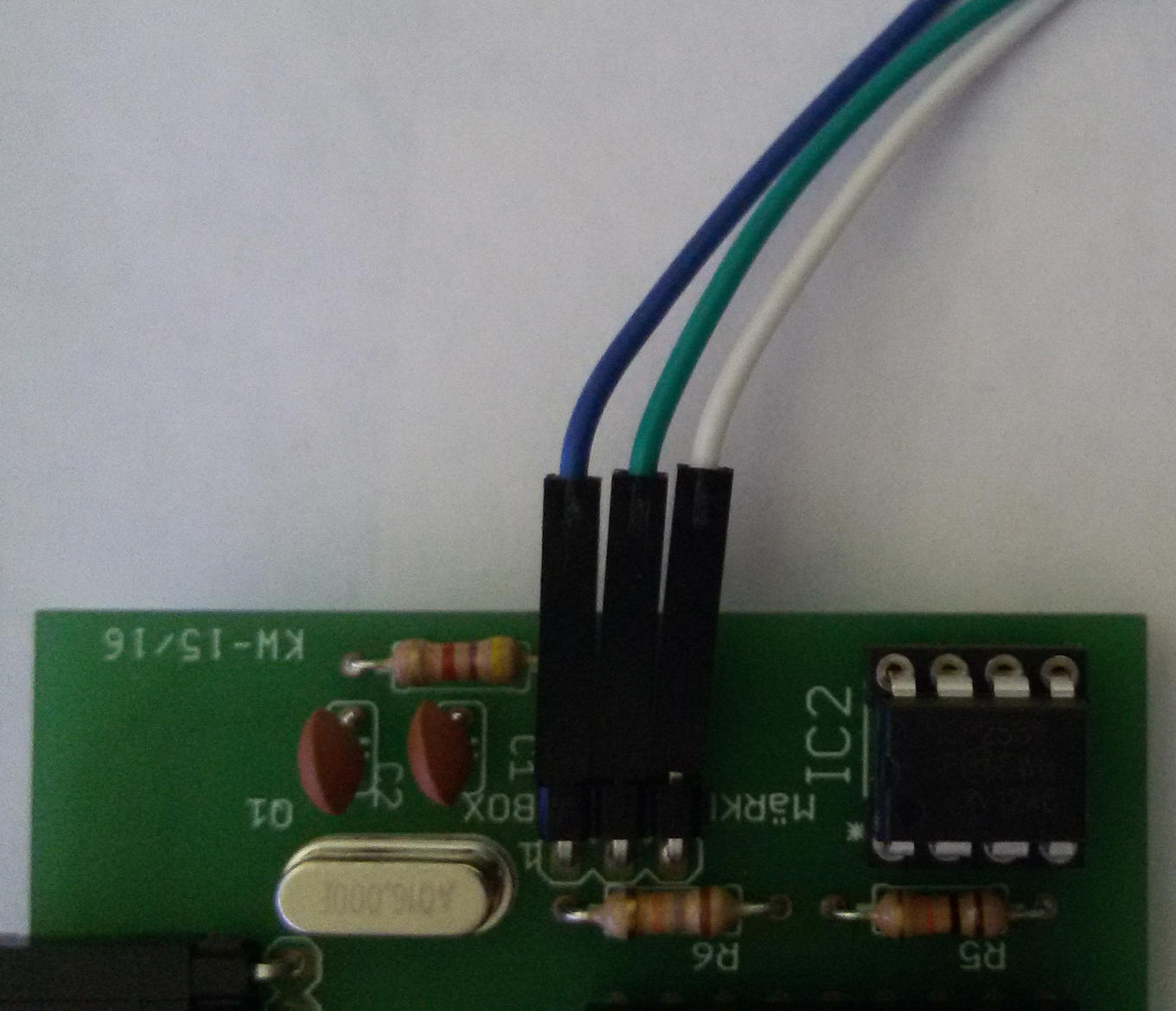
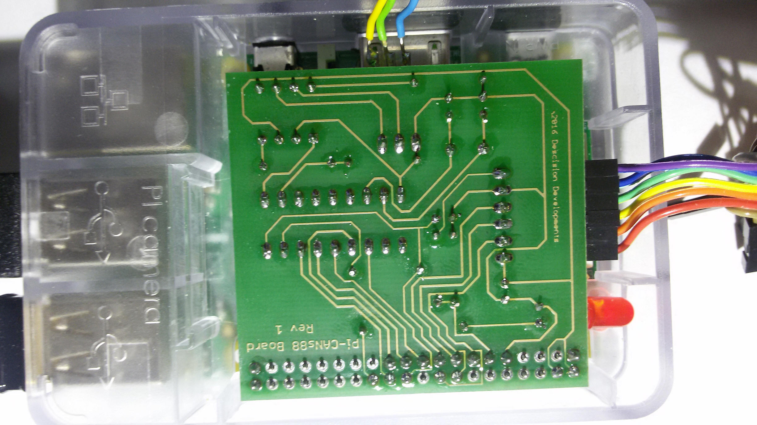
Mounting on a circuit board:
Parts side:
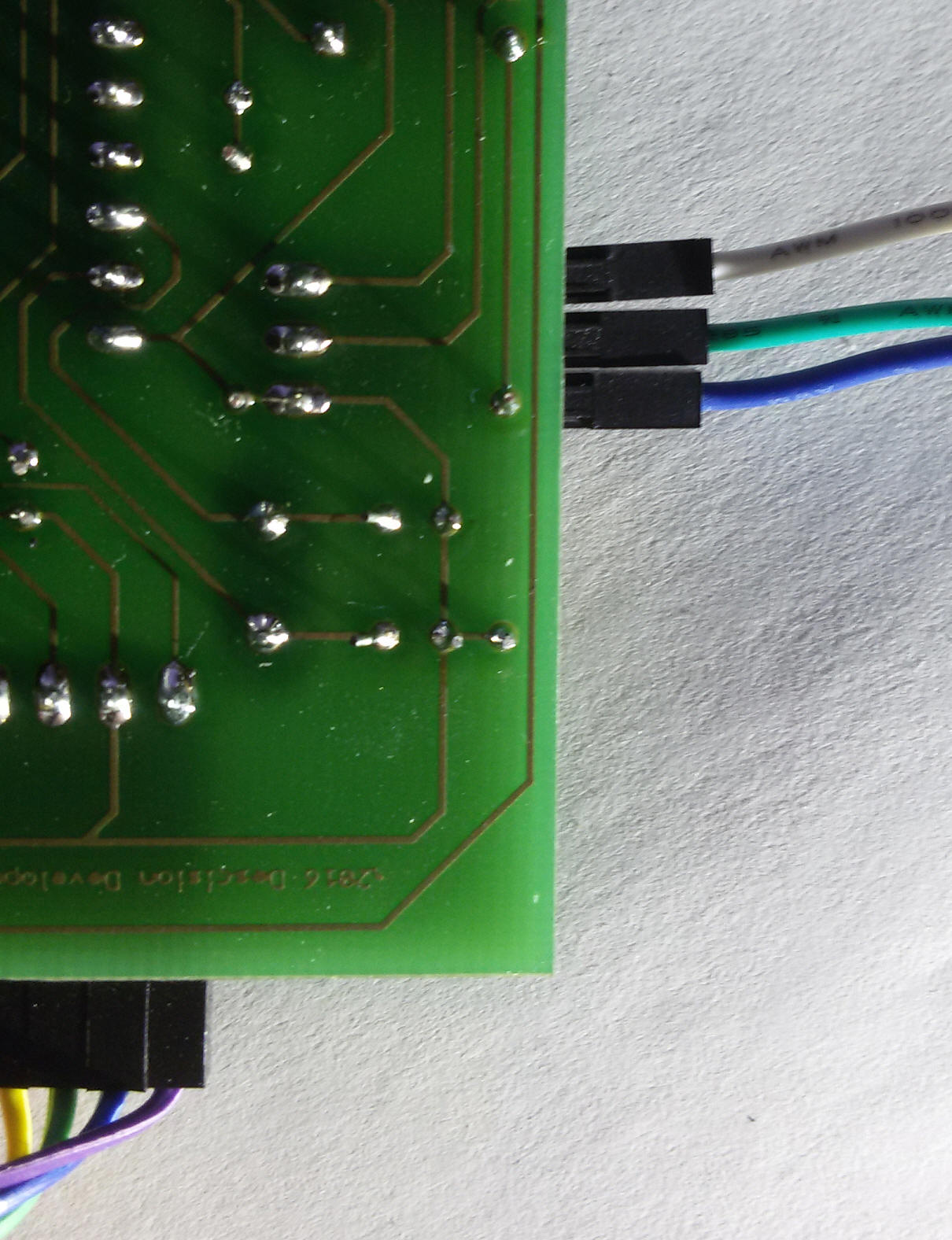
Soldering site:
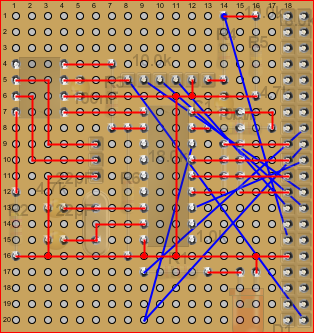
The blue connections can only be wired using isolated wires. I have been using a
Wiringpen for that.
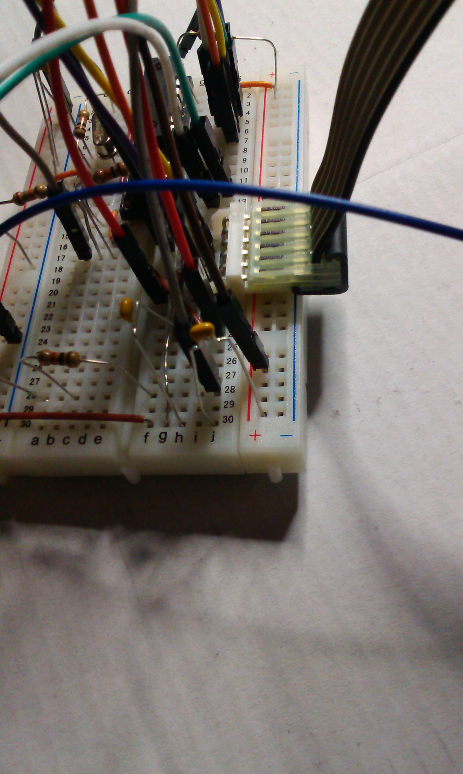
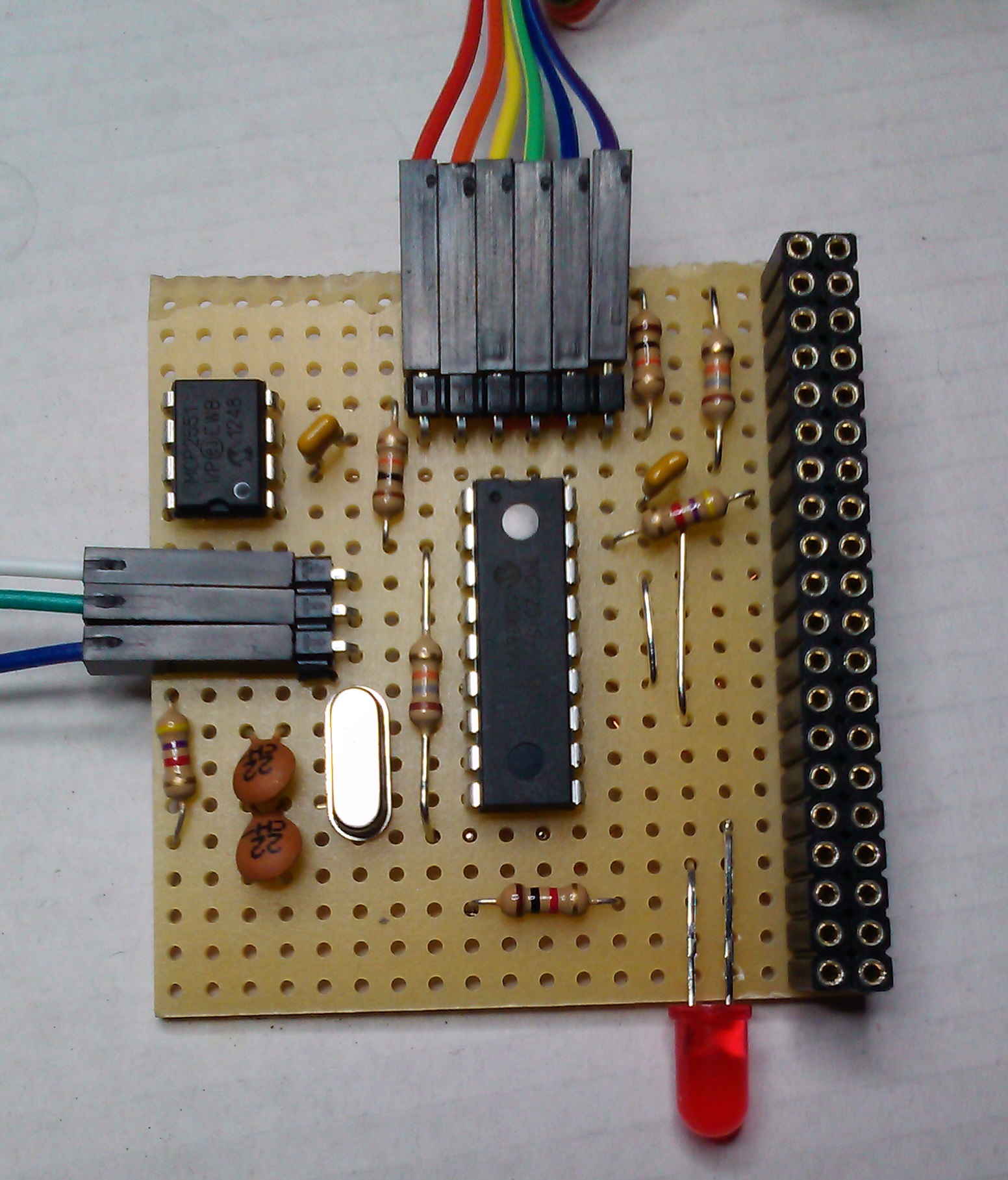
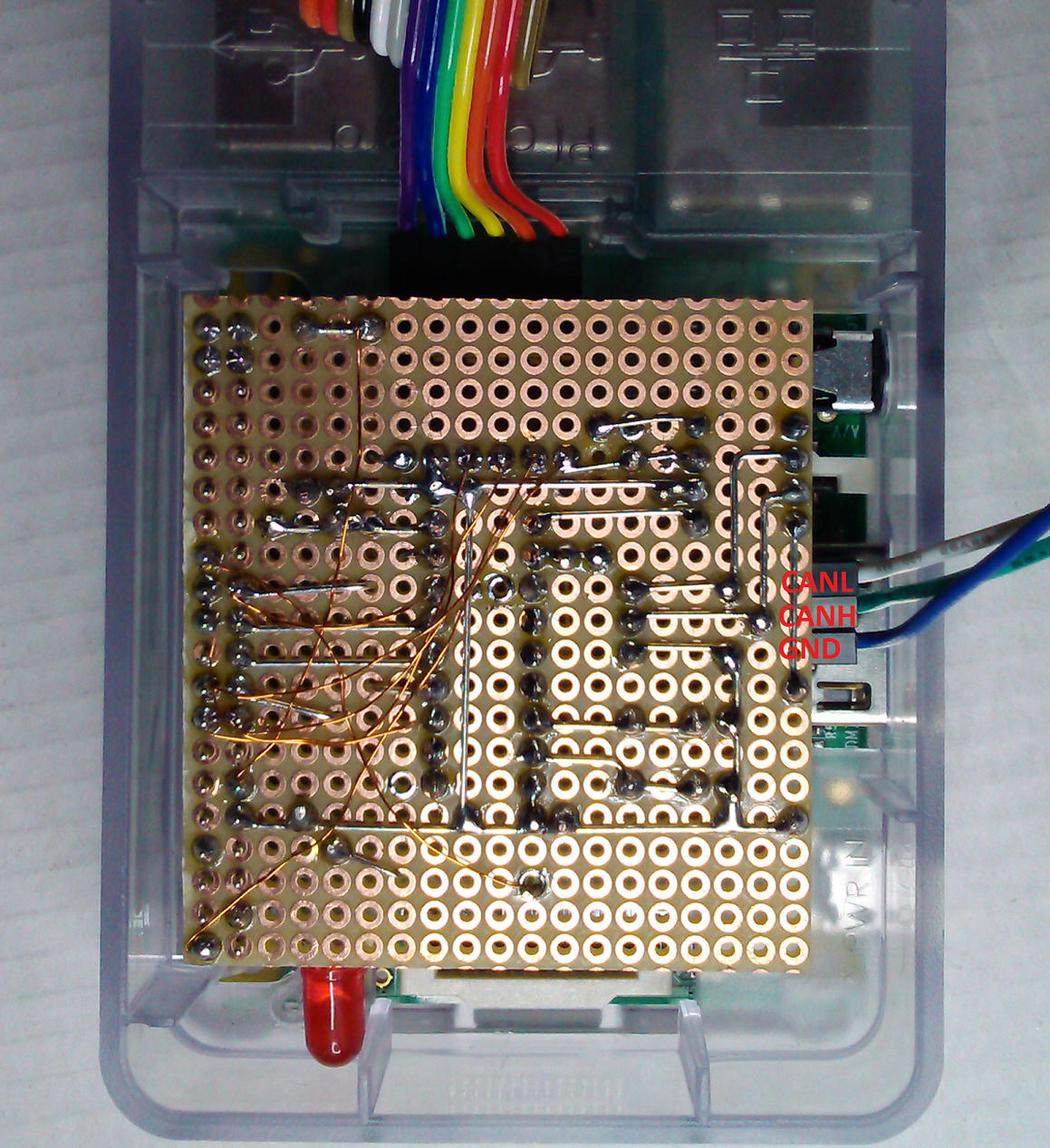
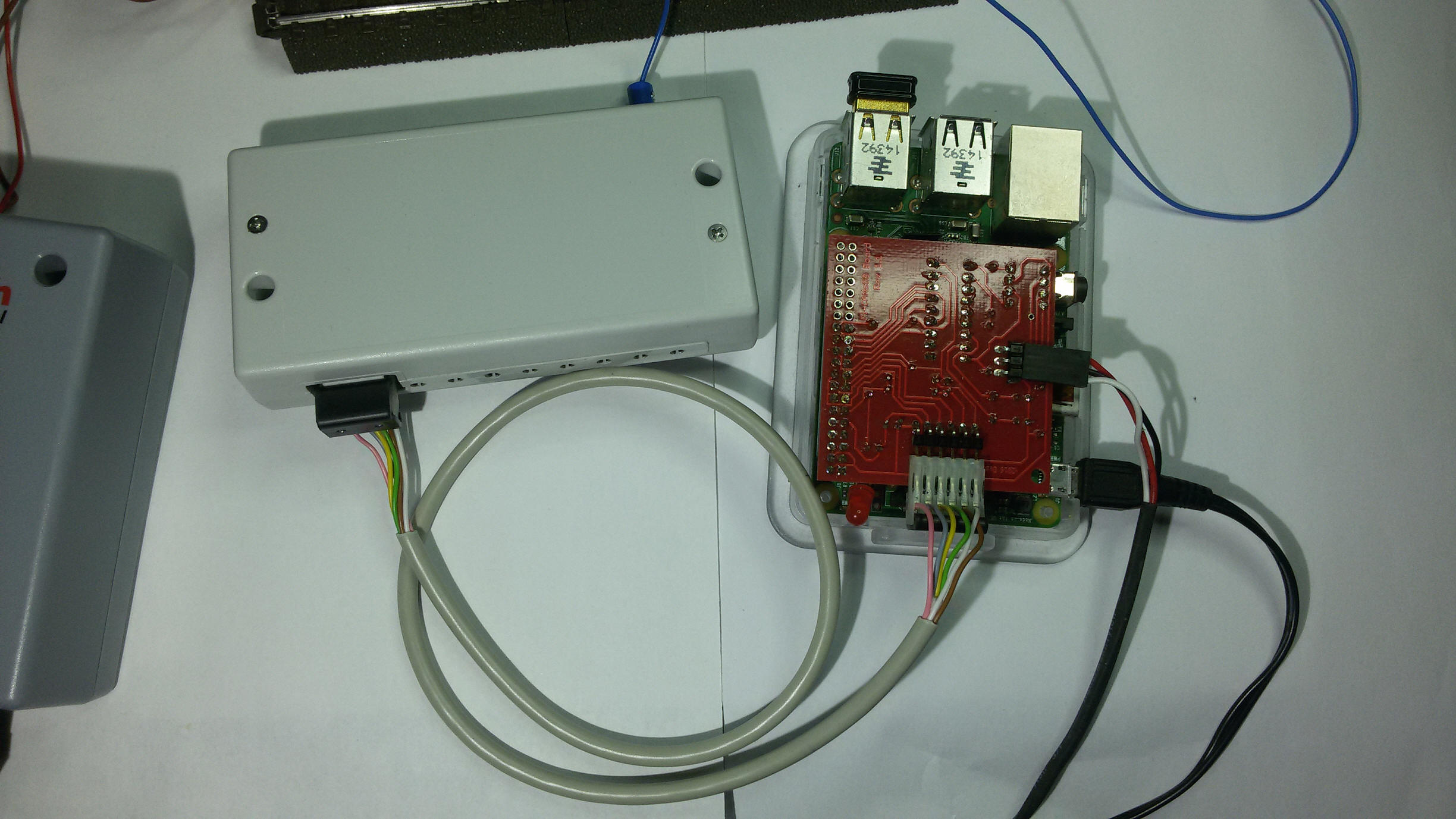
Live picture:
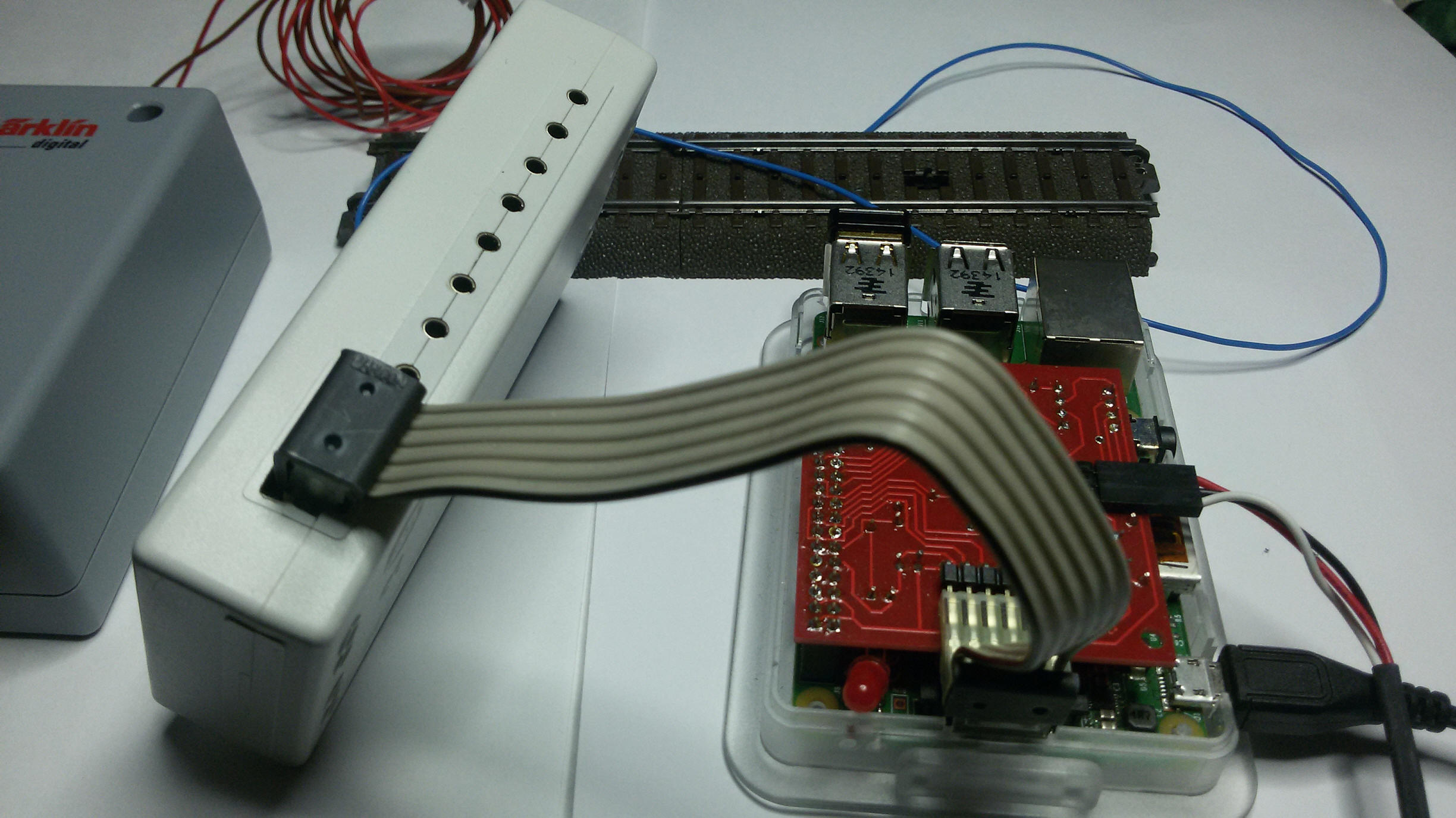
Attached to the Raspberry PI:
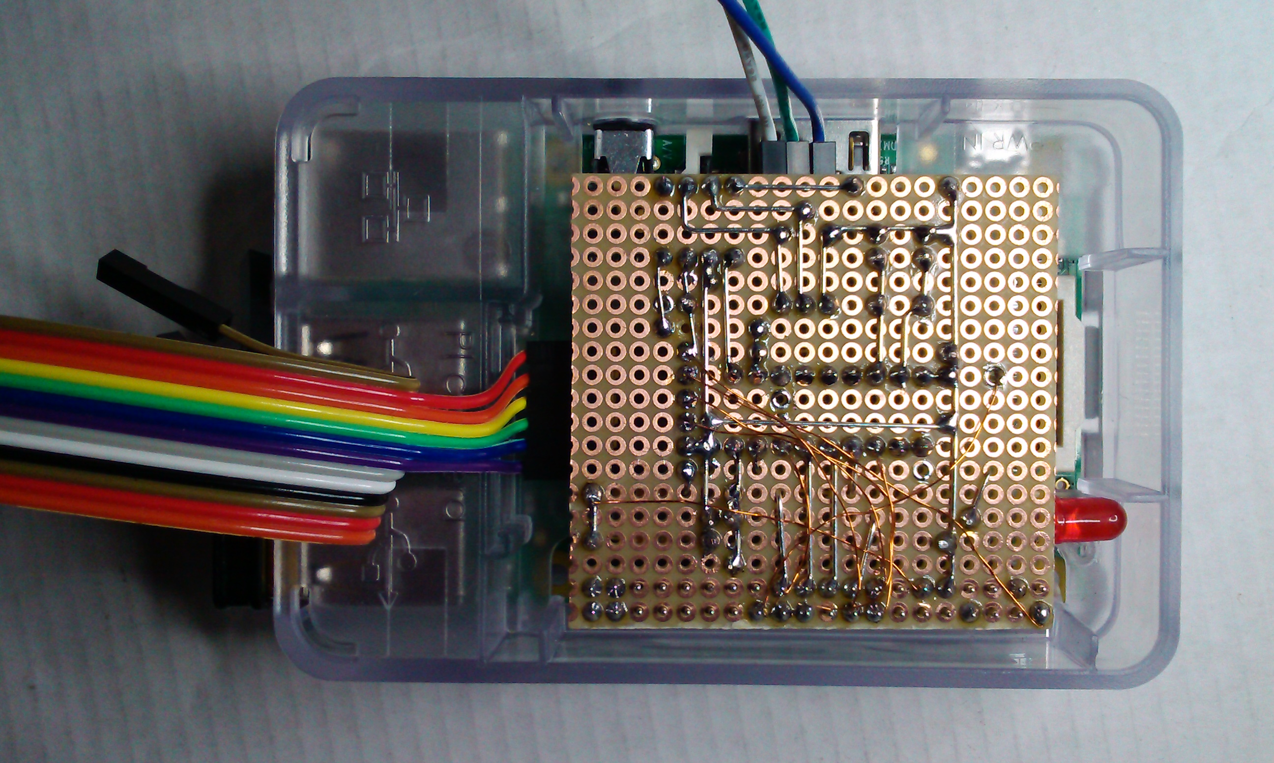
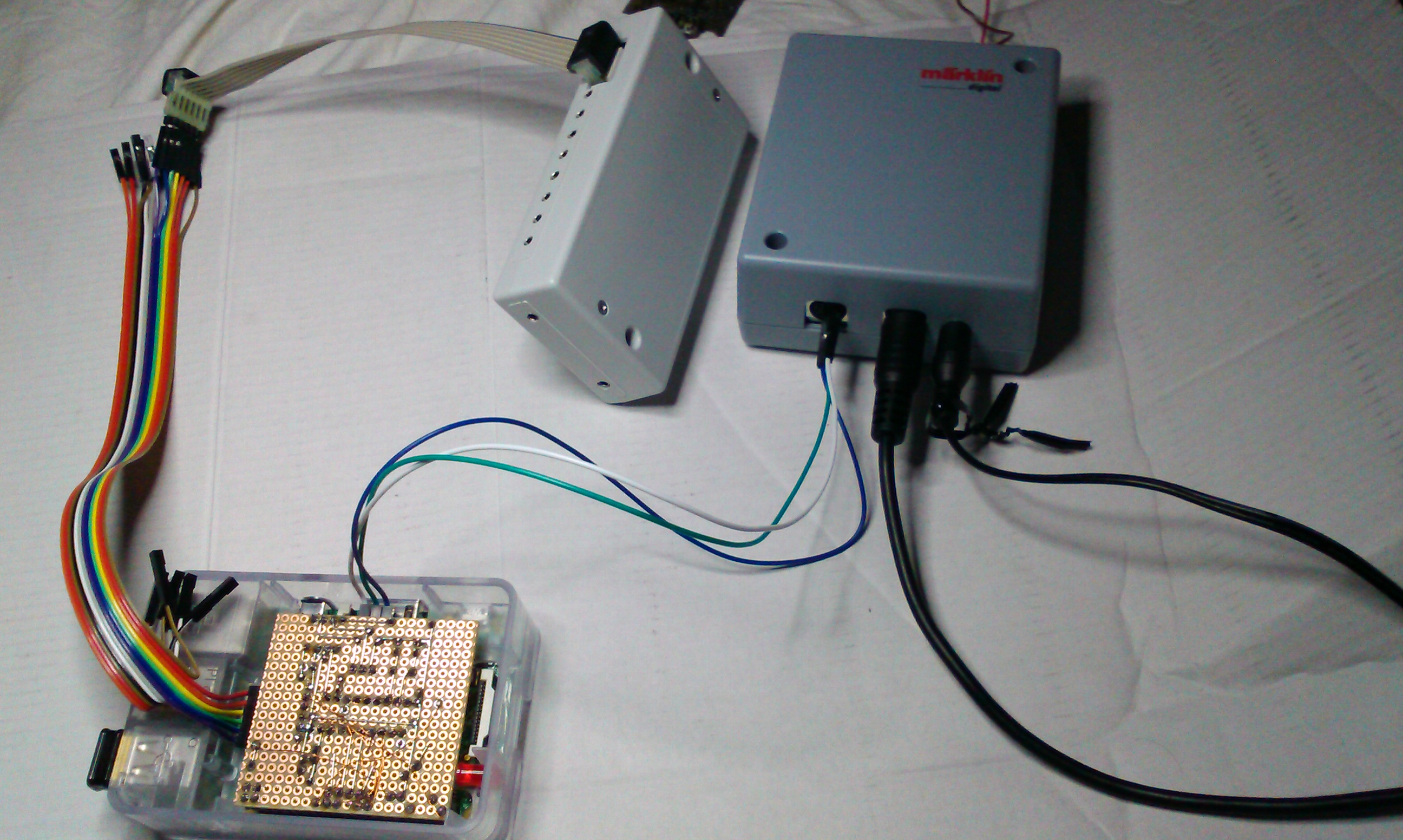
Complete connection example:
Note
about Mfx Lokos:
Getting the address of a MFX Loko can be tricky. Below I am
presenting two ways to find the right address.
Retrieving Mfx Loko Addresses:
Method 1 using MS2:
Using a Märklin Mobile Station 2 and my program for the Pi: PiCanS88,
you can retrieve the address of a MFX Loko.
After you have completely setup your Pi using my instructions,
you can manually start my program on the Pi with following command:
sudo
/home/pi/PiCanS88/PiCanS88 -f -b 192.168.2.255 -v -d 192.168.2.96
Of course you'll have to adjust the IP and Broadcast address
to your environment.
Now you can see all data communications of the CAN-Bus on your screen.
Connect a MS2 if it is not already present, and make sure the
"STOP" Button is lighting red, and place your "new" MFX Loko on the track.
Now press the "STOP" Button to put current on the track, and the MS2 will be
finding the new Loko, and give it a new address.
If this succeeds, and you are able to control the MFX Loko with the MS2, then
you can find the address using the output of my program.
For example, if you press the key on your MS2 for the
Headlights for this Loko, you can see following output on the screen:
->CAN>UDP CANID 0x0C2F17 R [6] 00 00 40 07 00 01
CANID 0x000C2F17 Prio: 0x00 Cmd: 0x06 Resp: 0x00 Hash: 0x2F17 DLC: [6]
Command: Lok Funktion: Loc-ID: [00004007], Funktion: [00], Wert: [01]
This Value: Loc-ID: [00004007],
is telling you that this Loko has the address: 7 !
"Loc-ID" stands for "locale Address ID", not for Loko ID !
MFX Addresses are using the area from 0x4000 to 0x7FFF, that's why the Loc-ID is:
0x4007.
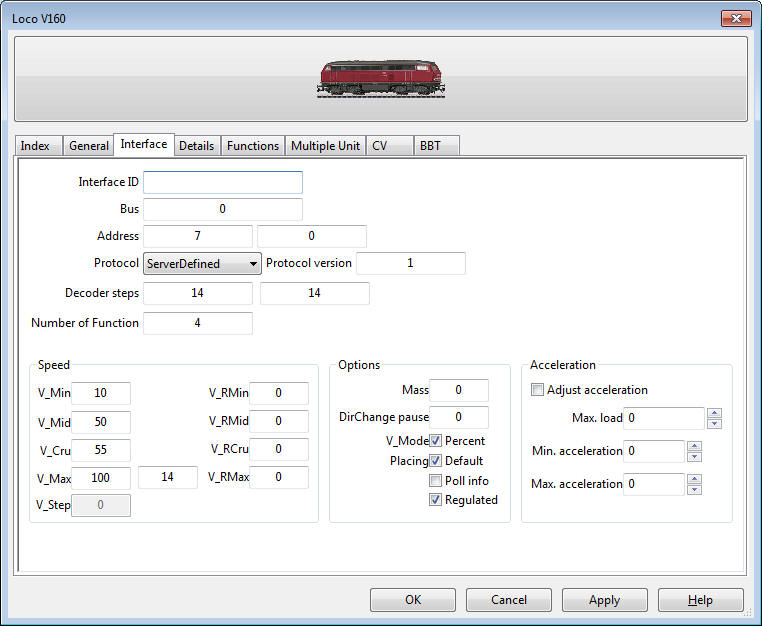
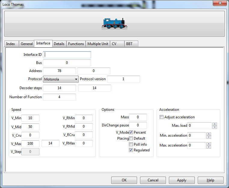
Pay attention: The address 7 is a Hex-Value! But in Rocrail you have to enter
the decimal value, so use the Windows calculator in programmers mode to convert
values between hex and dec.
Because hex 7 is also a 7 in decimal, you can enter a 7
as Address in Rocrail for this Loko, and use as Protocol: ServerDefined:
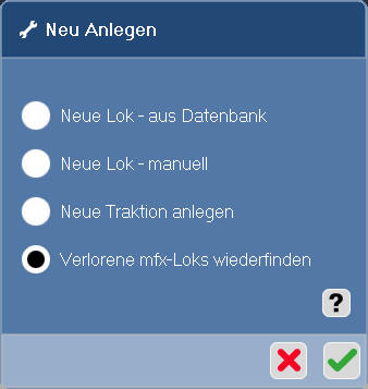
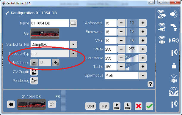
Method 2 using CS2.exe:
After you have installed the Software CS2.exe using my instructions
here, you can let CS2.exe search for lost/new MFX Lokos:
When the search has finished, your Lokos should be visible
here:
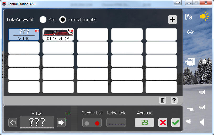
Click on the Loko you want the address of, and click the
properties button:
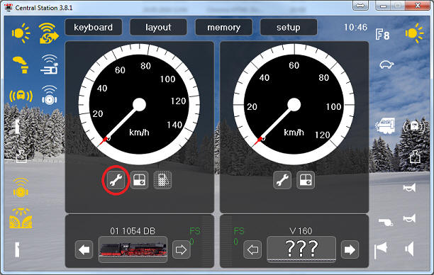
Now you can see the mfx-Address:
Software part:
To control using Rocrail you'll need a program which I created
out of these following Open-Source
programs: can2udp and s88udp
A step by step instruction of installing the software part on
a Raspberry PI is now available right here.
Done!
Now you can control your model railroad usinga PC over Raspi
with Märklin Gleisbox and S88 Feedback modules, completly with Rocrail.
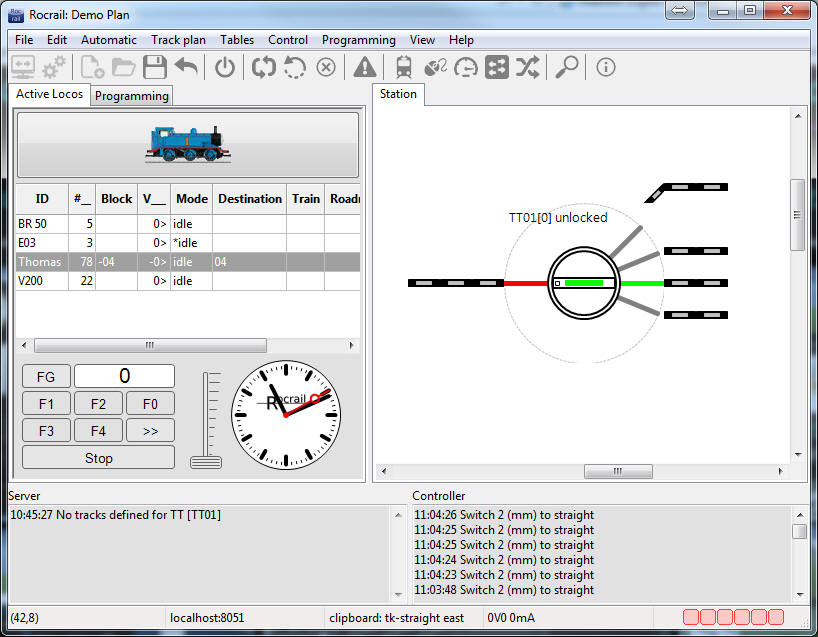
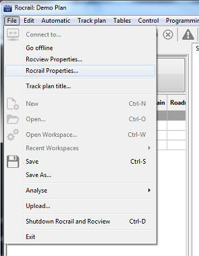
Settings in RocRail:
To use with Rocrail, you just need to tell Rocrail the IP Address
of your PI
as CS2. I have both, Rocrail Server and Client on my PC.
So choose following menu: File -> Rocrail Properties:
Switch to the tab "Controller":
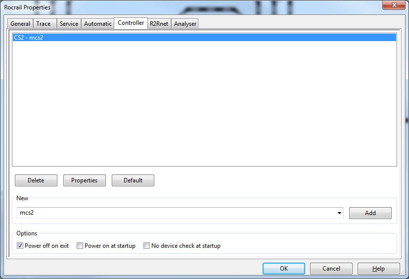
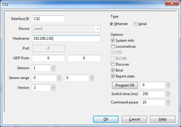
In above example, the CS2 is already configured, so click the Button: Properties,
and under Hostname enter the IP Address of your Raspberry Pi:
It's important that you pick Version "2" as in above
picture.
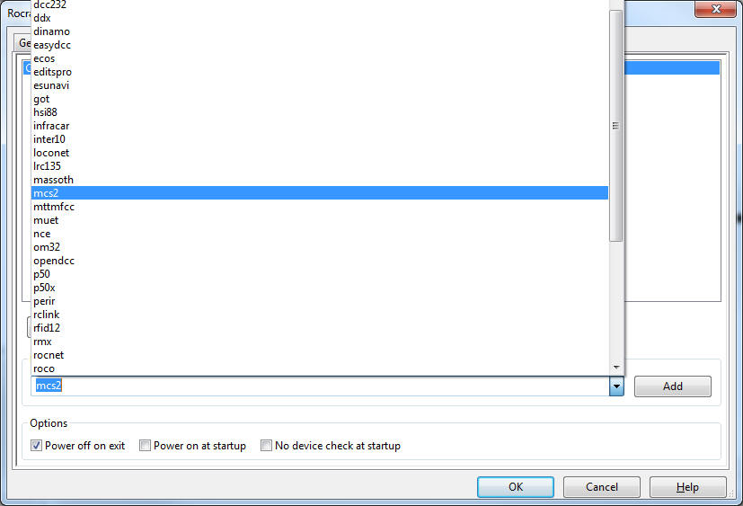
If you don't have already a controller configured, please
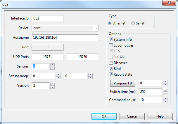
choose as new controller type "mcs2", and click the "Add"-Button:
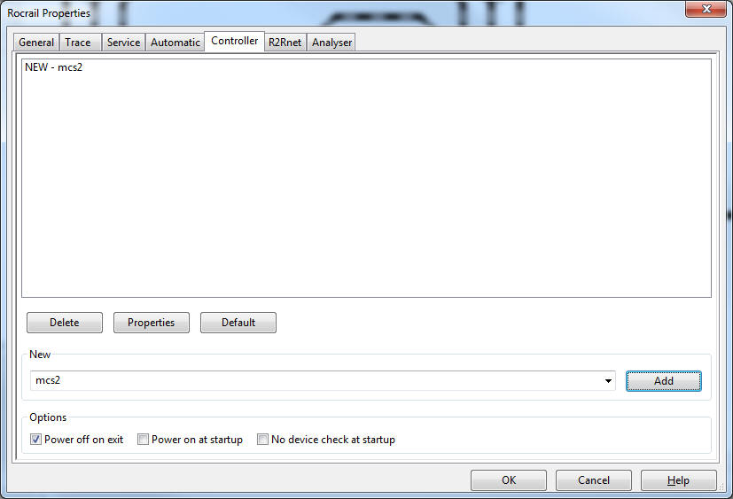
Select the newly created entry: "New - mcs2", and
click the
Button Properties:
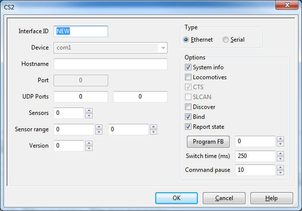
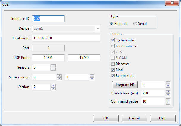
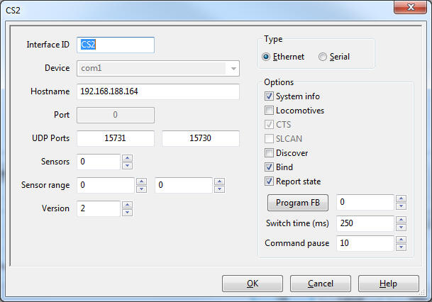
For Interface ID you can choose any name you like. I will use CS2.
At Hostname enter the IP address of your Raspberry PI. As
Version pick "2", and at Sensors enter the amount of S88 feedback modules, you
are going to use. For our first testing purposes, we will use: "1":
The values for the UDP ports can stay at 0, then Rocrail will
use the default values 15731 und 15730.
Done!
Rocrail is now configured to use your Pi as central
station. Before your trains can roll, you will need to adjust the right Address
for each Loco:
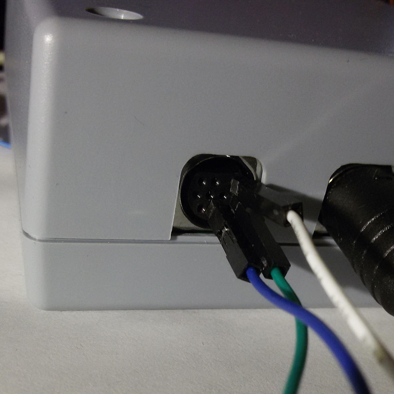
Connecting to the Märklin
Gleisbox:
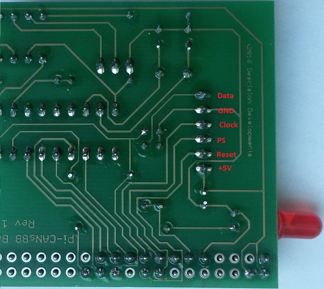
Connecting a S88
Feedback Module:
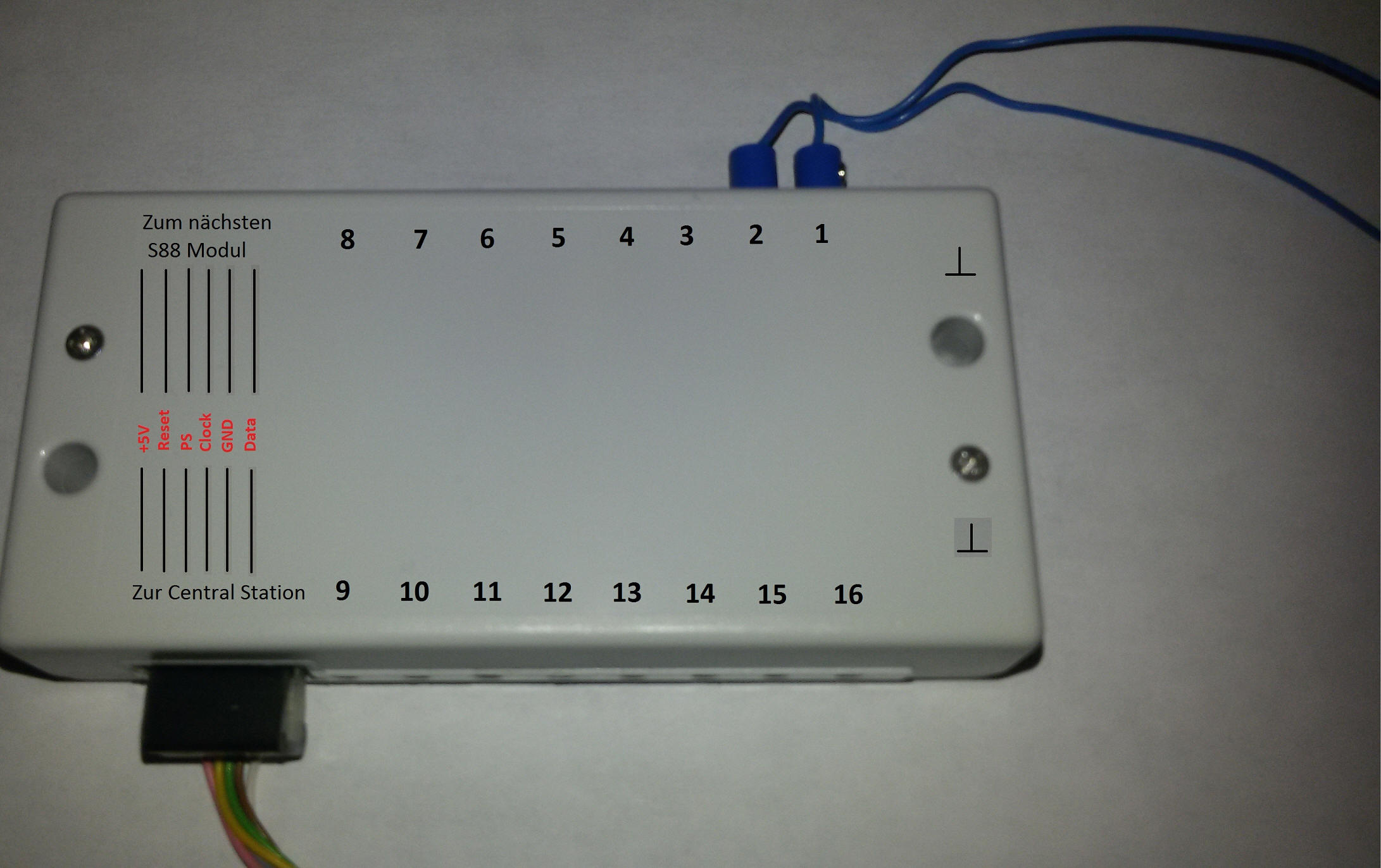
Here is a picture with the pin-out on my board for the S88 bus.
And here is the pin-out of a typical S88 Feedback Module:

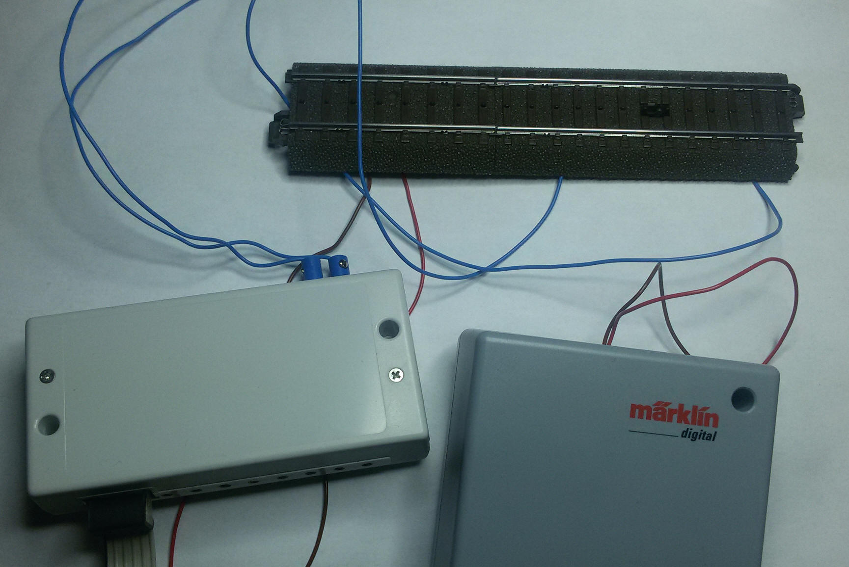
Both connected look like this:
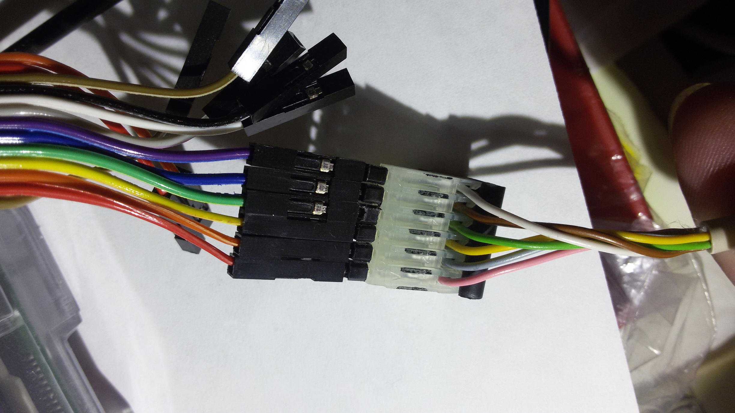
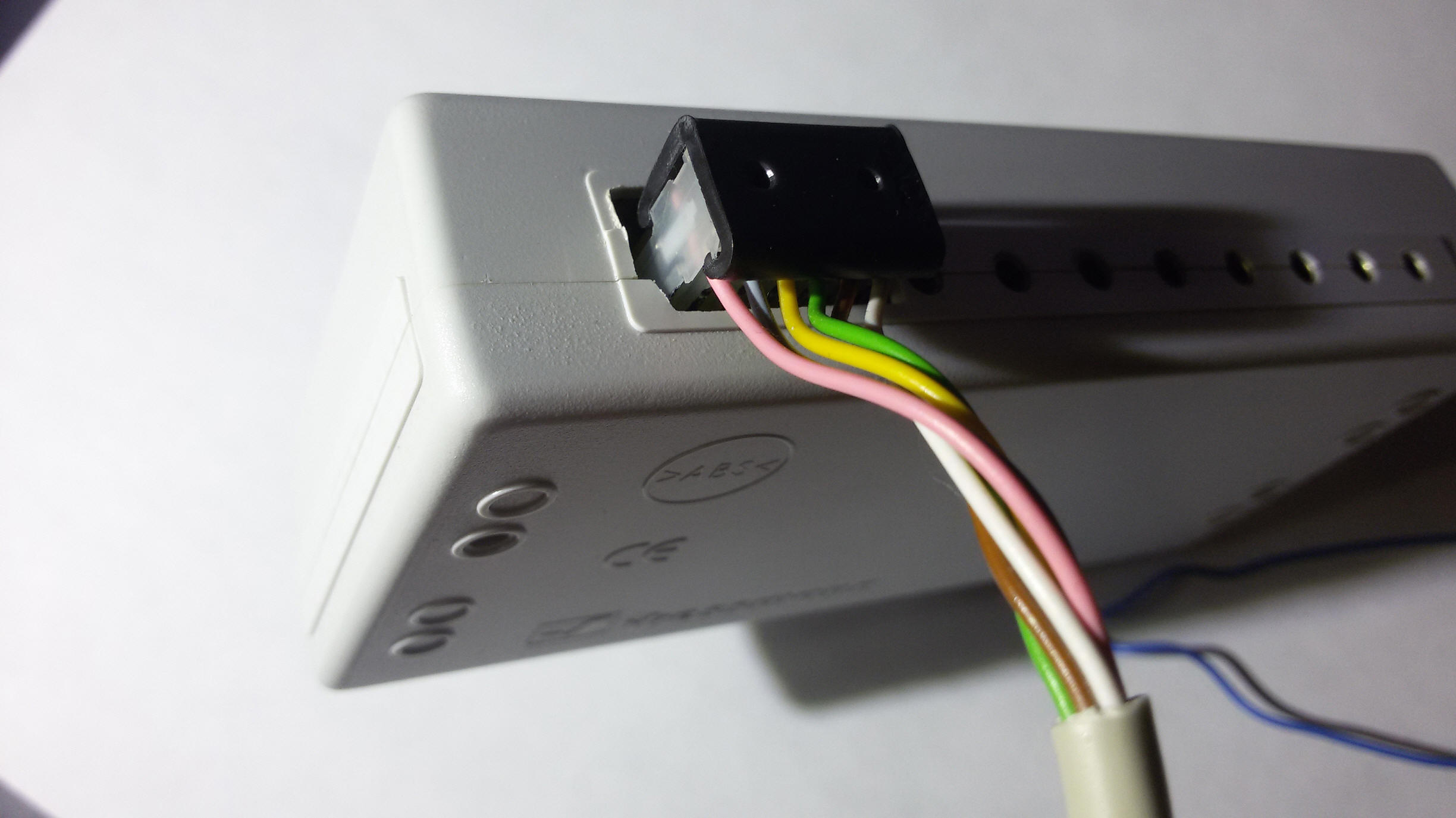
or so:
or with Littfinski LDT-Cable:
Simply pay attention at the +5V position. On my board it's located close to the
LED, and on the S88 module it's located to the outside to the end of the box.
Note: With my Board and the Gleisbox you don't need to connect "GND" of the Module
with the track. If you are using a real CS2, then you will need to connect "GND"
with the track, which is labeled "0" for C-Tracks,
because the CS2 has no connection between the circiut of the track and the S88
modules.
Update: Do not connect the "GND" of the module with the
track, because it causes a shortcut and could destroy your Pi.
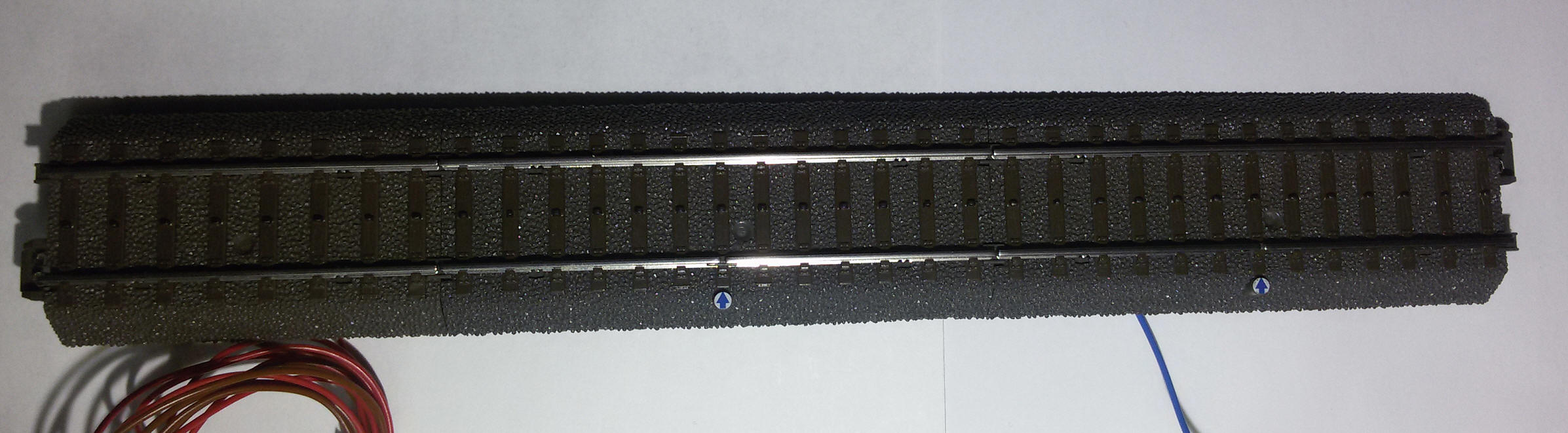
For testing purposes we will now connect a "C-Circuit Track" at the ports 1
und 2 of the feedback module.
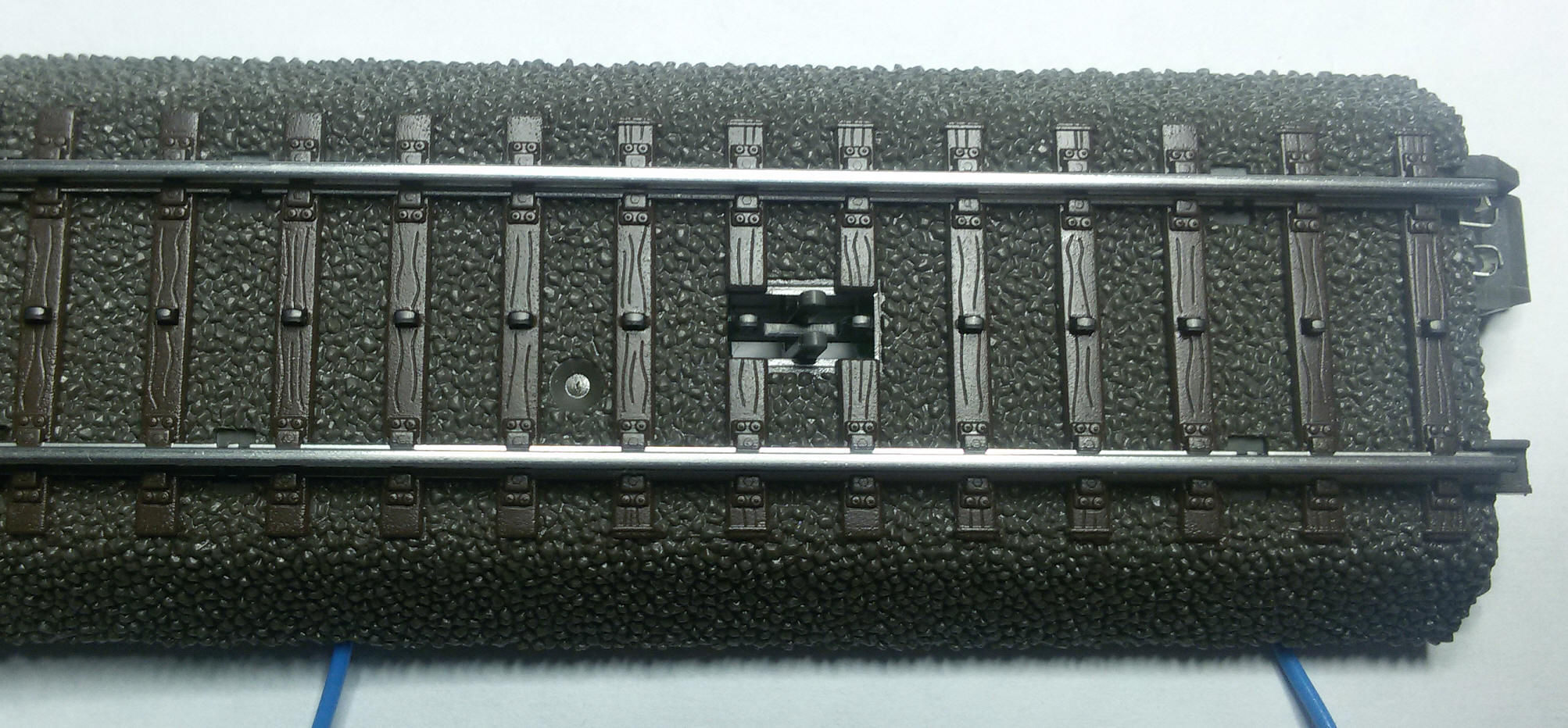
U can also use a contact track set:
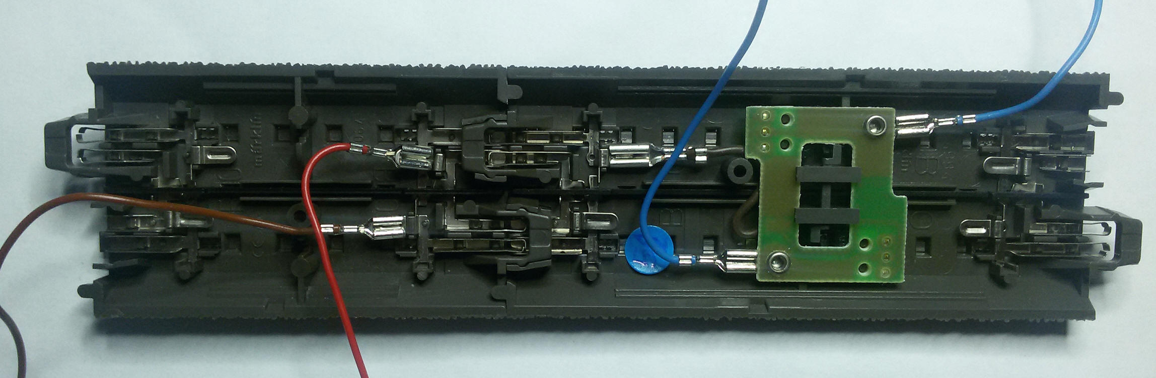
Connecting module RM-88-N
from LDT:
Attention: Do not connect the "GND" of the module with the
track, because it causes a shortcut and could destroy your Pi.
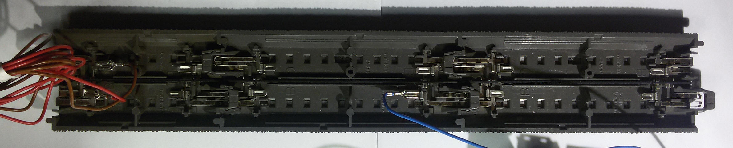
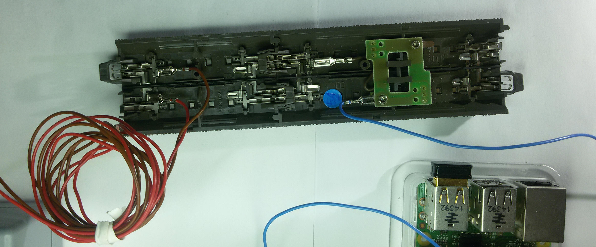
Connecting module RM-88-N-O
(Opto) from LDT:
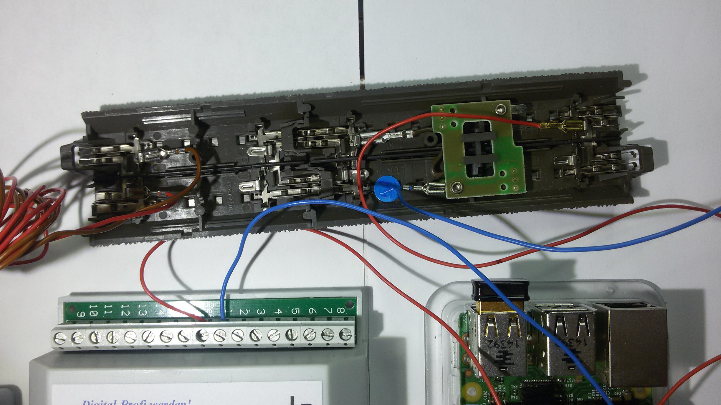
As you can see, with this module you will need another connection with the
track, which is using the red cable, connected to the module at the mark: "Ref",
and with the track at the mark: "B".
Configuring S88 in Rocrail:
Now lets tell Rocrail that we are using one S88 Module here: Rocrail-Properties -> Controller -> CS2 properties:
Change the number of Sensors to "1":
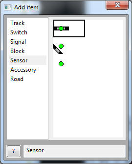
Click the "OK" Button and then we will add 2 sensors into our track plan with
the menu: Track plan -> Edit panel
There you pick "Sensor", and drag and drop any sensor type to your track plan:
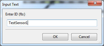
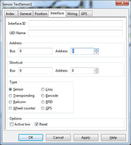
Now you will be asked for an ID. I will choose: "TestSensor1":
Now open the properties of this new sensor, and switch to the tab "Interface":
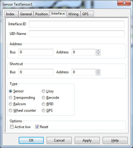
The curciut track is connected with both sonsors in Nr. 1 und Nr. 2 of the
module,
which is also the address of the sensors. So we enter a "1" at Address -> Address:
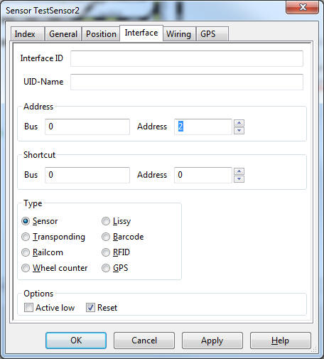
Do the same for sensor Nr. 2:
Mine looks now like this:
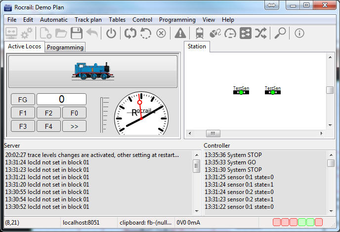
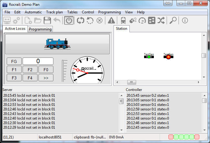
If you now turn on the power on the track with this button:

And if you now use the switch on the circuit track with your finger, then one of
these two signals will turn red:
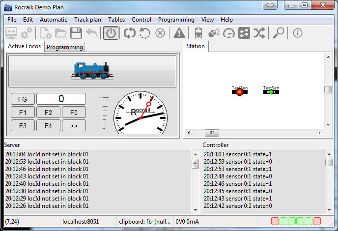
Now I moved the switch onto the other side:
Usage of
tams s88-N Adapter S88-A:
Those who like to use standard network-patch-cables for their S88-Connections,
can use those fantastic
S88-N Adapters from tams.
(tams have been so kind to spend all four variants of their adaptors for this
manual :-) )
But take caution:
There are four different versions of those adaptors, and you have to take
caution about the arrangement of the pins of each one!
Sadly the description which comes with those adaptors is very poor, and the
adaptors themselves have no print on them to get a clue which pin has which
connection.
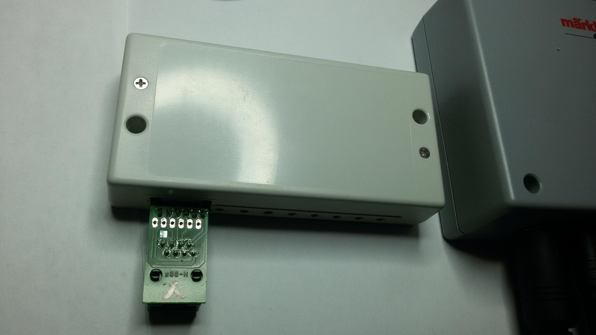
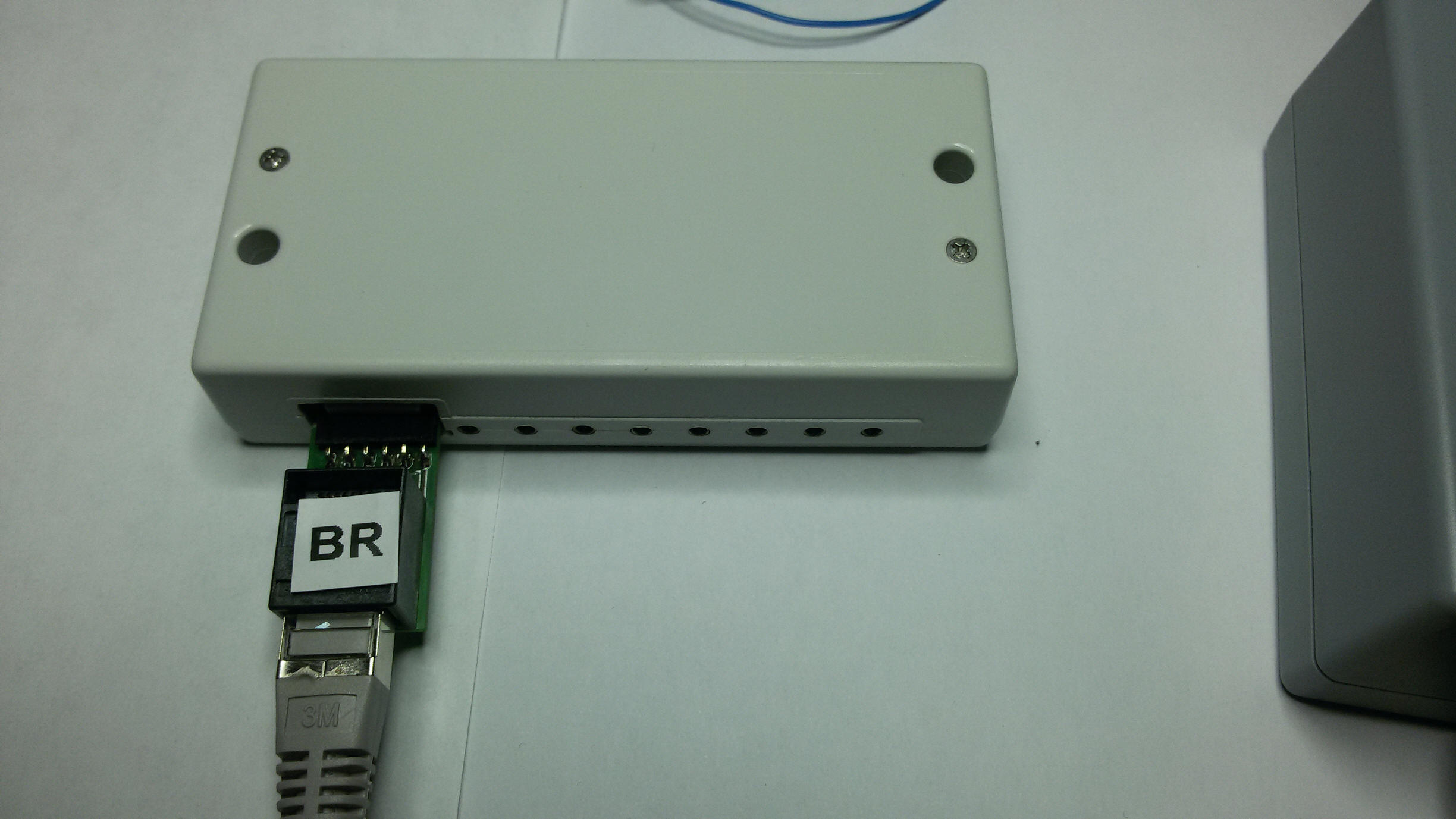
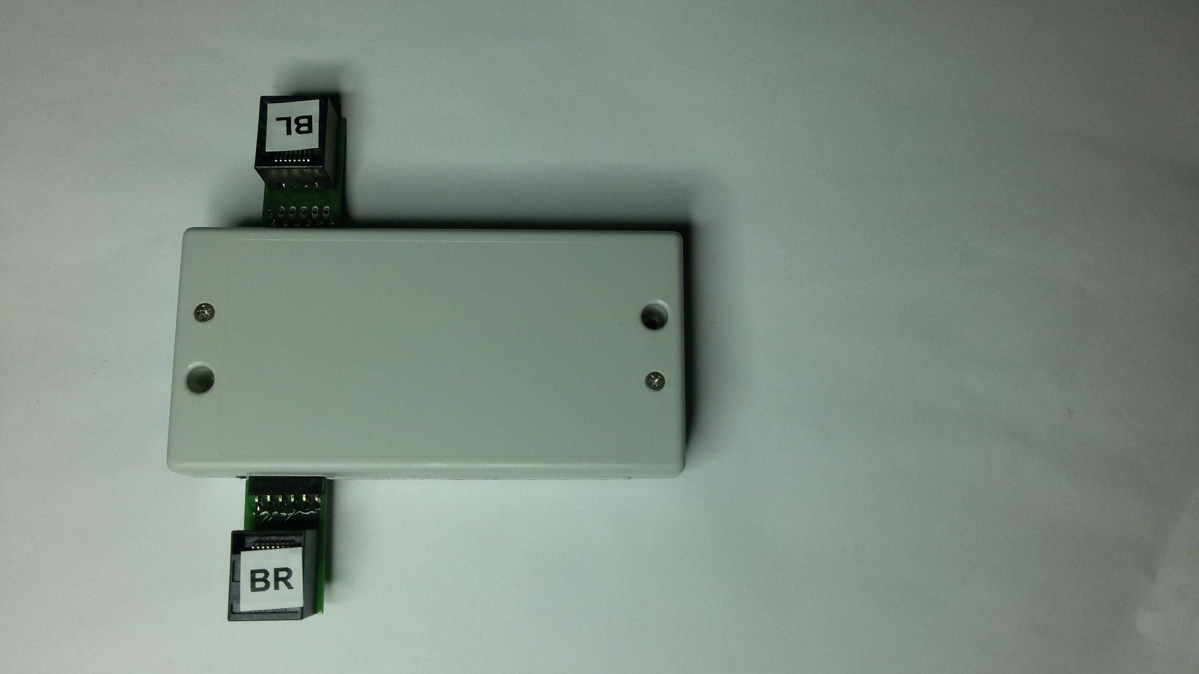
So I made a picture of each model, and present you the pin-out of each model:
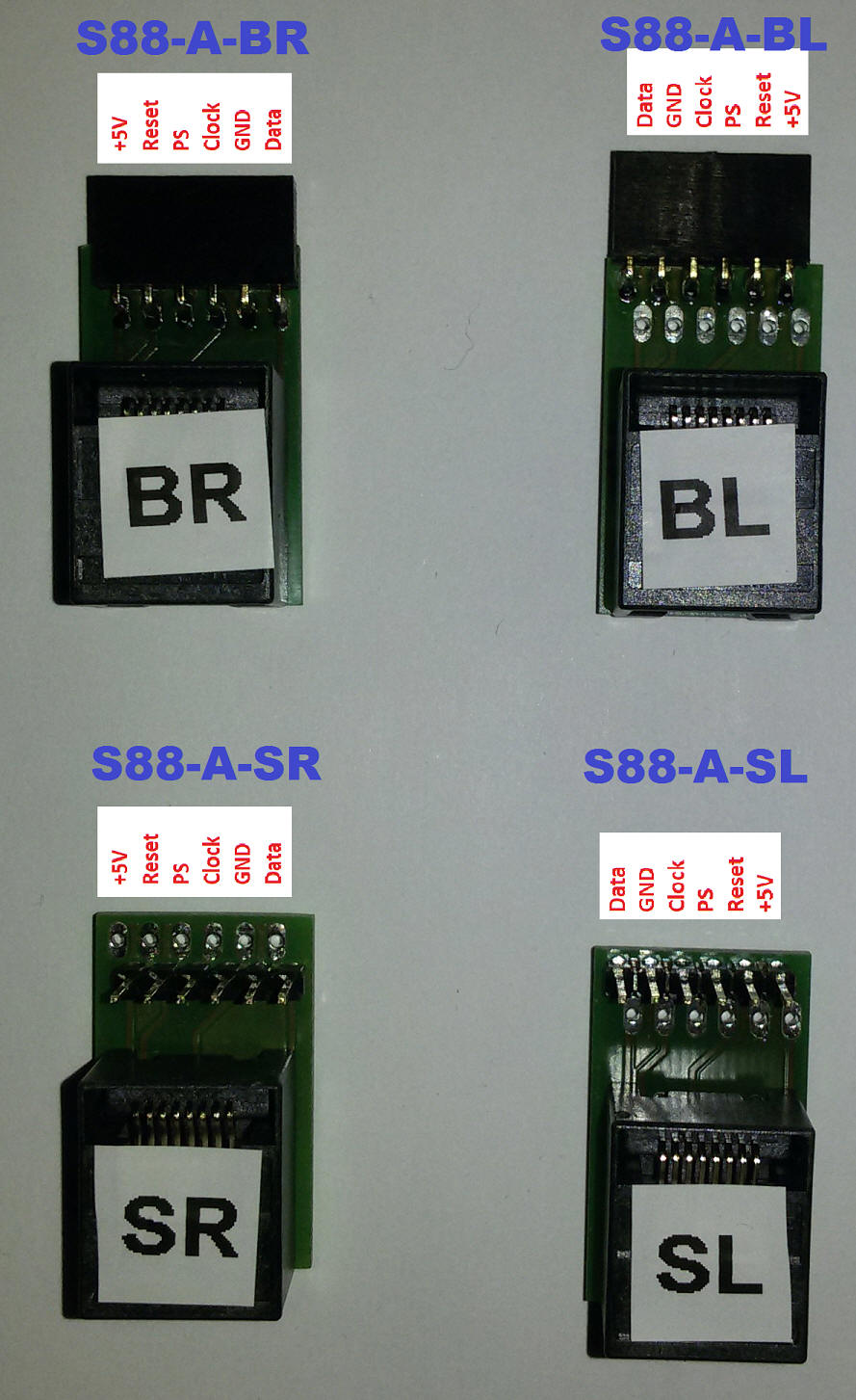
I did place a label on each model as you can see in above picture: "BR", "BL",
"SR" und "SL", because it's easier to know which one is which if you have more
of them.
I recommend you do the same if you buy more of them. Put a label on each one,
right after unpacking it!
Usually you will only need the adapters BL and BR, and the right usage would be
like this:
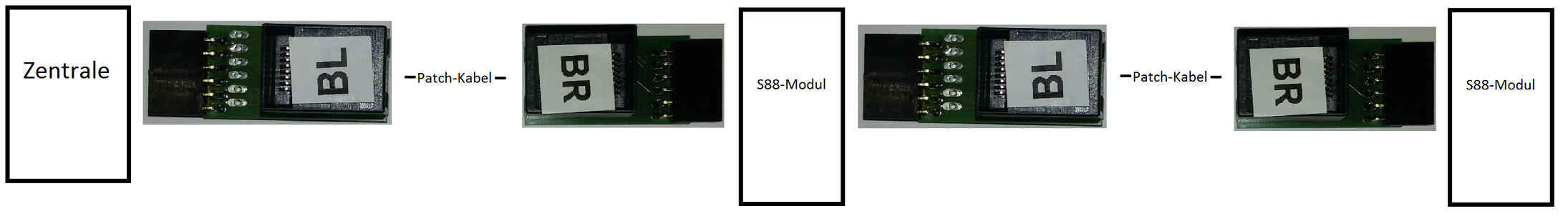
In case you need a S88 connector cable in between, the usage would be like this:
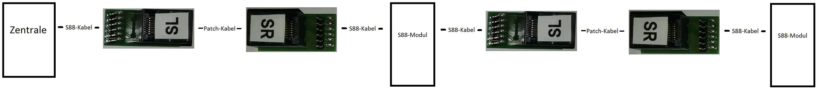
Because you can connect each adapter the wrong way, you
should be very careful and read the following usage examples.
To use those, the best is to orientate at the +5V Pin.
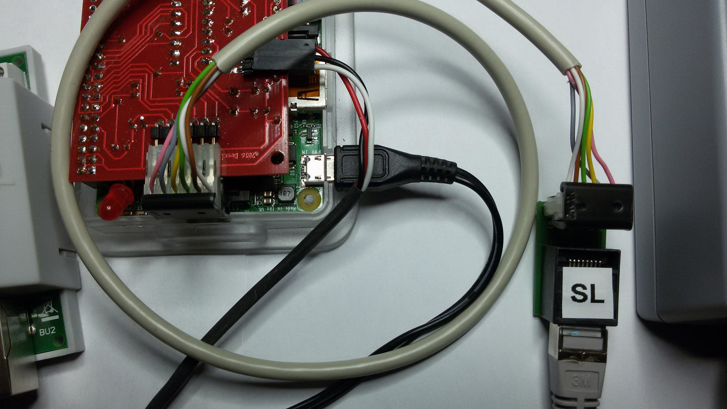
Find below some examples with pictures :
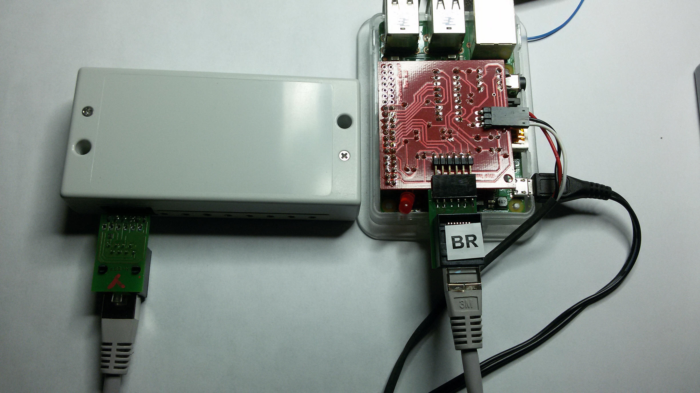
Using with a Pi with Adapter BR (Not meant to be used this way, but possible):
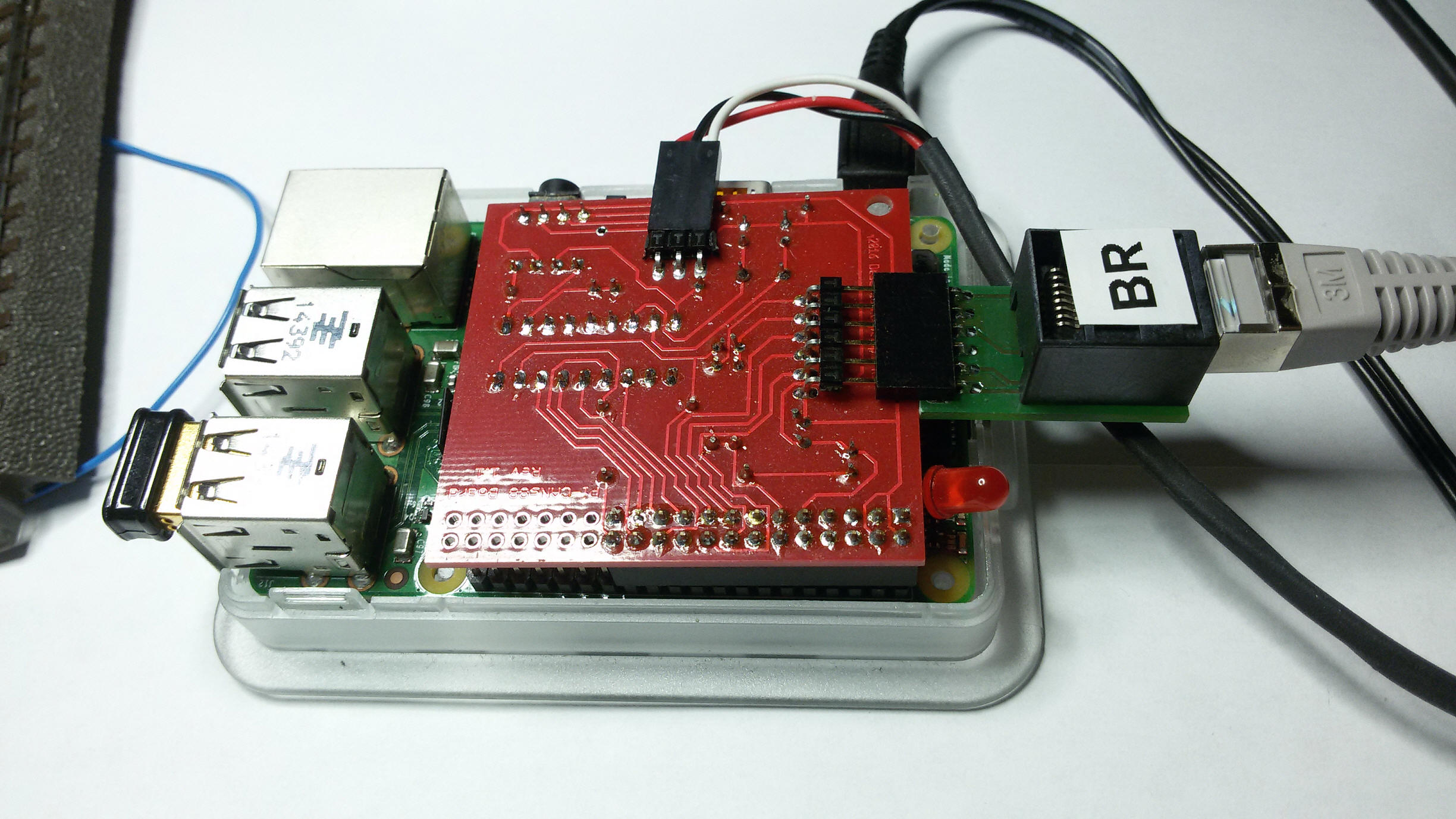
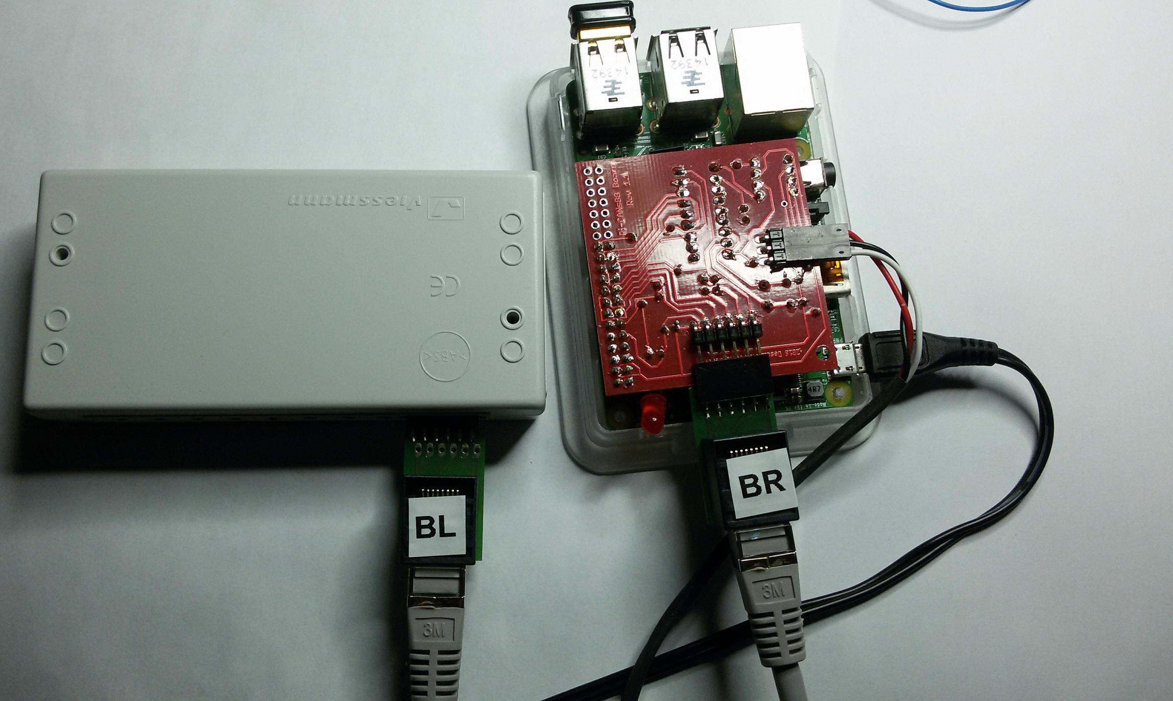
Correct usage with a Pi with Adapter BL:

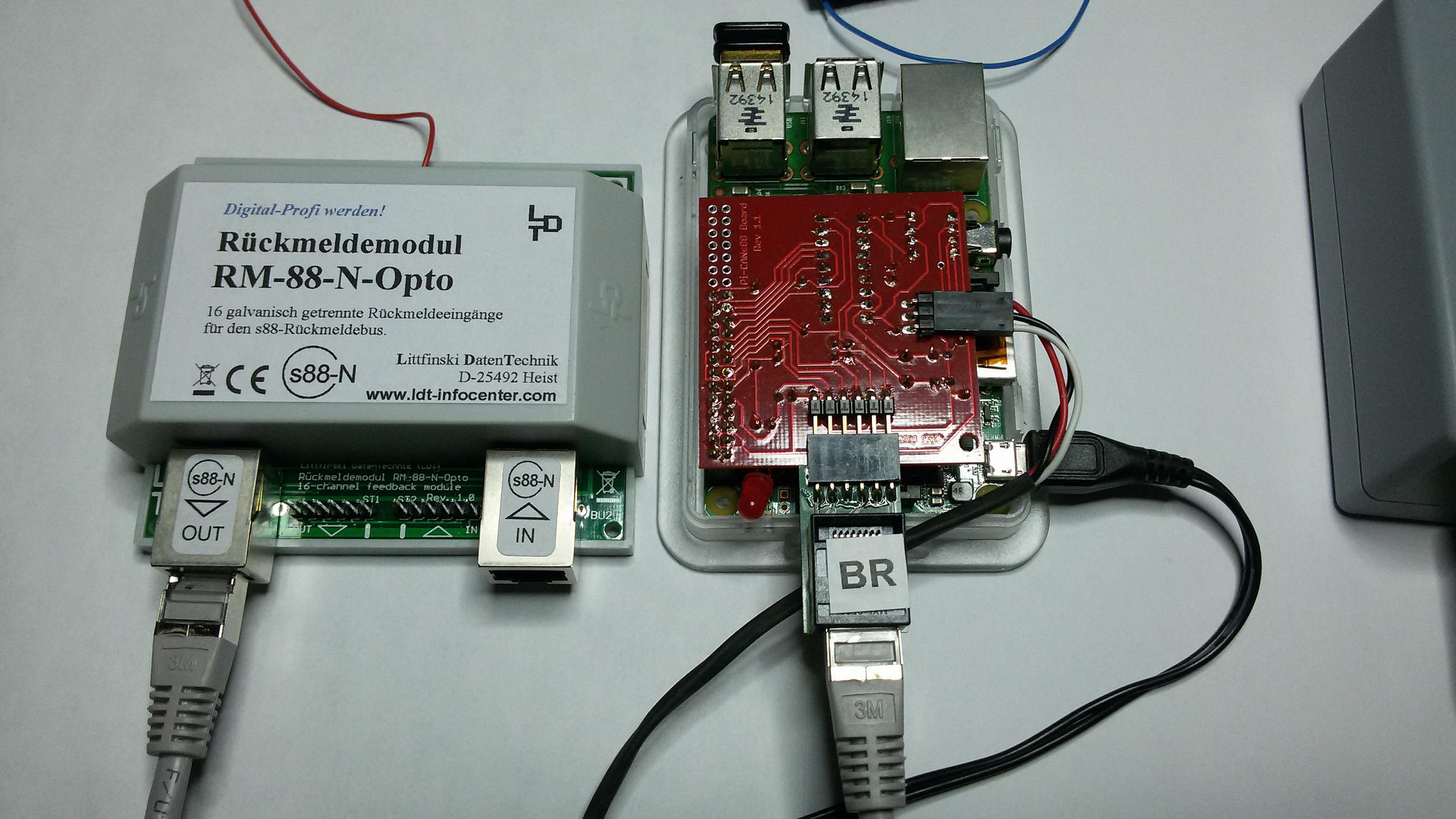
Using with a Pi with Adapter BR and a Littfinski Opto feedback module (Not meant
to be used this way, but possible):
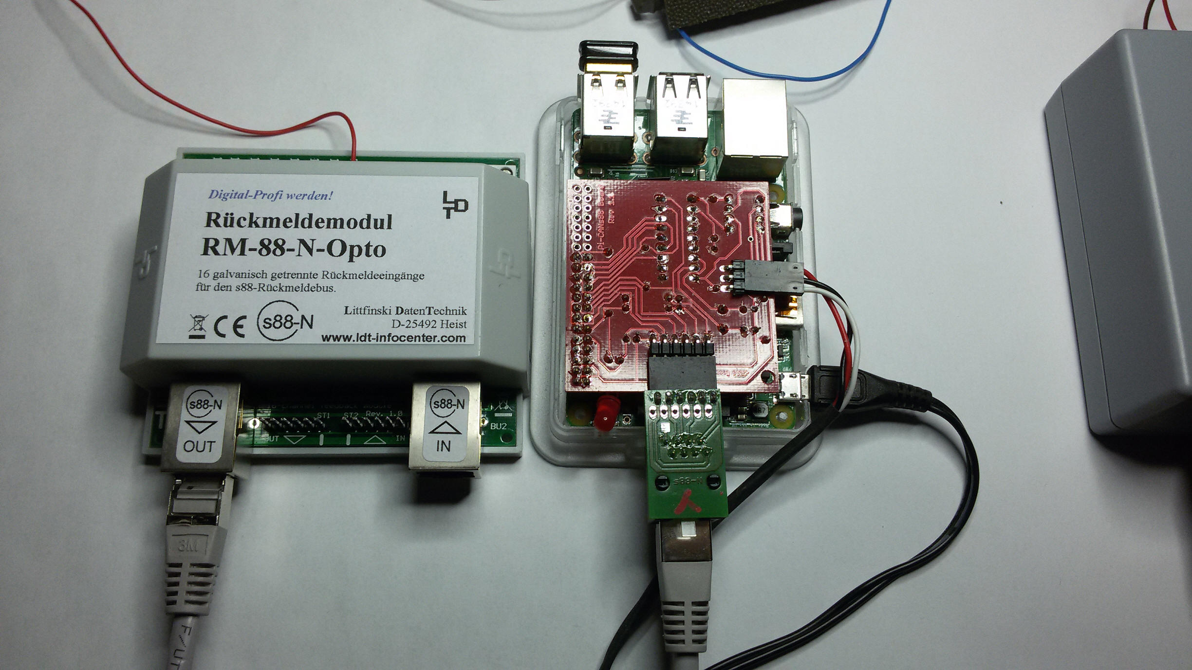
Correct usage with a Pi with Adapter BL and a Littfinski Opto feedback module:
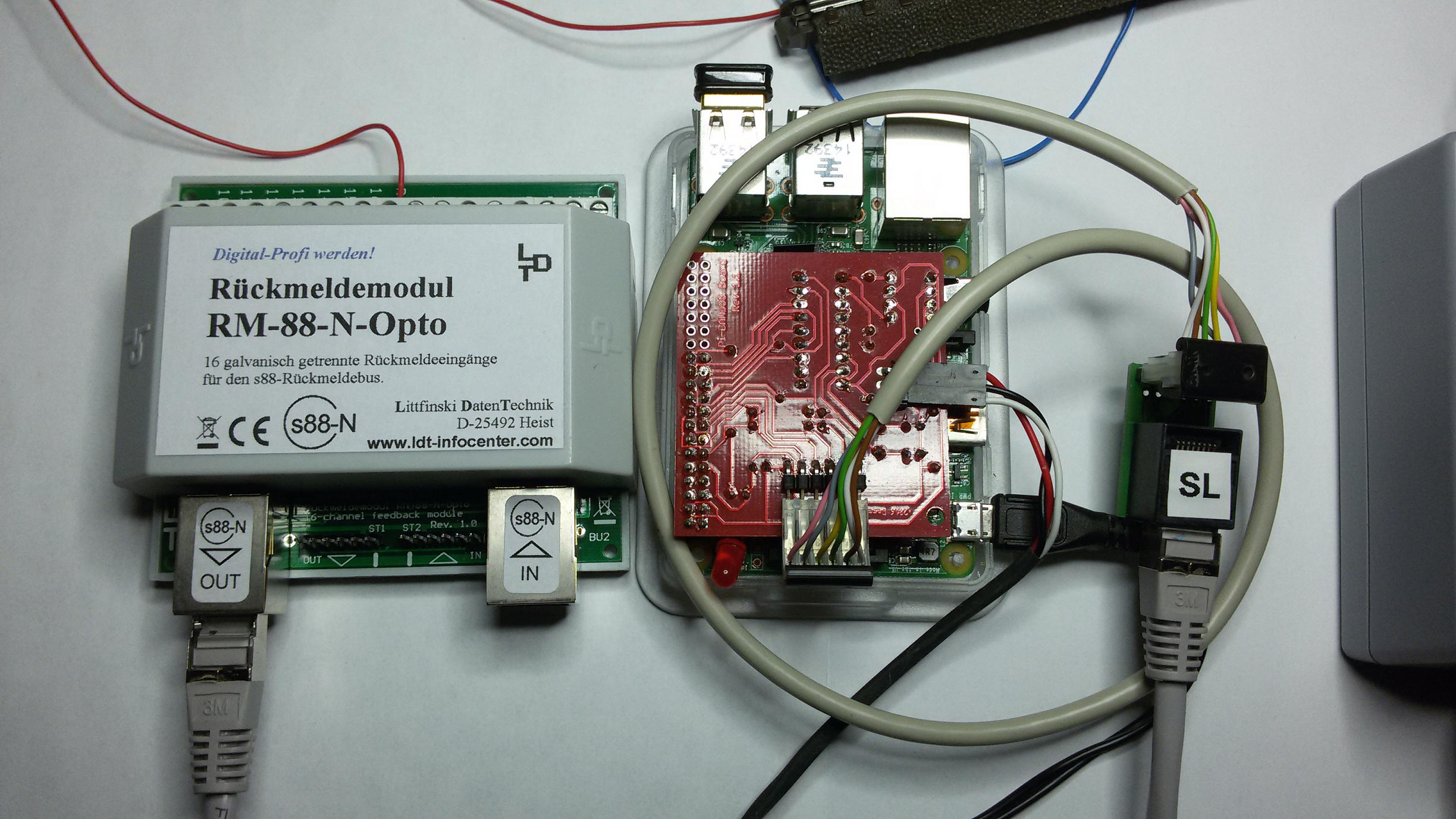
Using with a Pi with Adapter SL and a Littfinski Opto feedback module and
Littfinski connection-cable:
Using with a Pi with Adapter BR and a Conrad/Märklin feedback moudle and Adapter
BL at the feedback module (Not meant to be used this way, but possible).
Actually adaptor BL should be at the Pi and adaptor BR at the module:
Using the Adapter BL with a S88 Module to connect a central station/pi (Not
meant to be used this way, but possible):
Correct usage of Adapter BR at a Conrad S88 Module to connect a central
station/pi:
Correct usage of Adapters at a Conrad/Märklin S88 Module. Adapter BR goes to the
Pi, and Adapter BL goes to the next Module:
Attention:
Never ever turn around any of those adapters. Only connect them as shown
in the pictures above, otherwise you could destroy your module or central
station or Pi!
You can contact me any time if you have doubts about your doings.
S88 Y Splitter DSW-88-N
from LDT:
Here is an
interesting product from LDT, to split the S88 Bus.
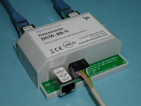
Picture-Source:
LDT-Website
Usually you have to connect all S88 feedback modules one after each other in a
row.
But using this devise you can split the usage.
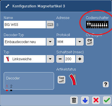
Configuring a Turnout Decoder 74460:
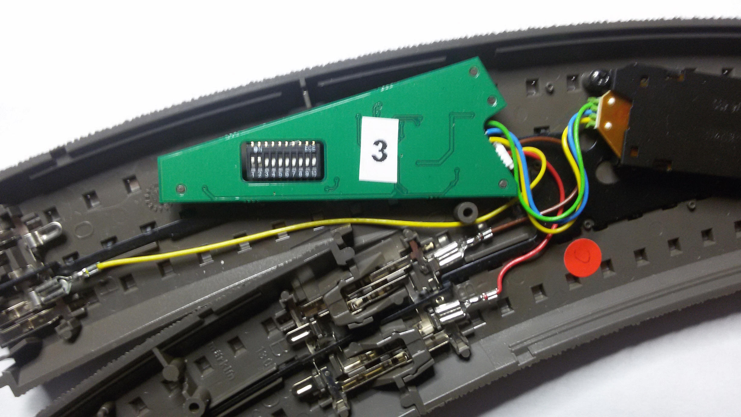
Setting the Address:
The little switches are the single bits, which will configure the final address.
All switches off are address: "0"
Switch 1 adds always 1.
Switch 2 adds 2
Switch 3 adds 4
Switch 4 adds 8
Switch 5 adds 16
Switch 6 adds 32
etc...
As you can see, the value always doubles
To setup address 3, we will turn switch 1 und 2 onto 'On' (because 2
+ 1 = 3).
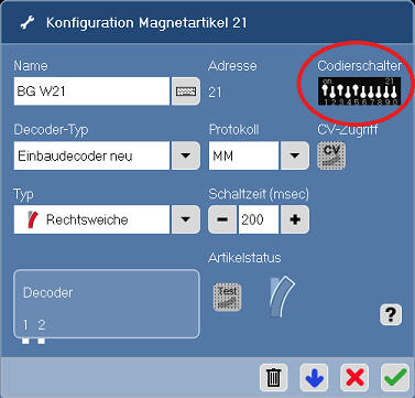
If you want address 21 then you would use 16 + 4 + 1, so that would be the
switches 1, 3 and 5 onto 'On'.
If you still have trouble, you can also use the configuration for turnouts in
the software CS2.exe, which will show a usefull picture of the right switch
postions:
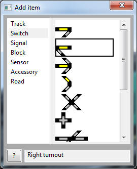
Adding to Rocrail:
Now lets add our turnout into our track plan in Rocrail with menu: Track plan
-> Edit panel
Choose Switch and drag and drop a turnout into the Track
Plan:
When asked for the ID, I use 'sw' for 'Switch' and the nummber of the address: '03':
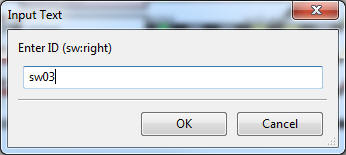
No open the 'Properties' of your turnout and switch to the tab :
'Interface', und enter the address as Port-Nummber !:
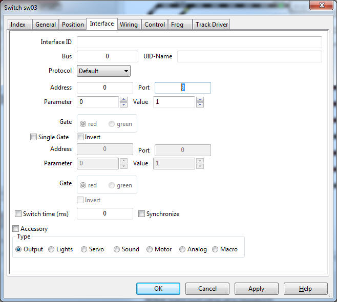
Click the "OK" Button and we're done! If you now click on the turnout in the
track plan, the turnout will be moving if the track power is on.
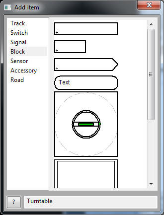
Configuring a Turntable 7286 with 7687
Menu: Track plan -> Edit panel
Choose "Block" and drag and drop a 'Turntable' into the Track
Plan:
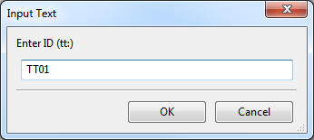
In the 'Properties' switch to the tab 'Interface' and enter as address "225", and
as "Type" choose 'ttdec':
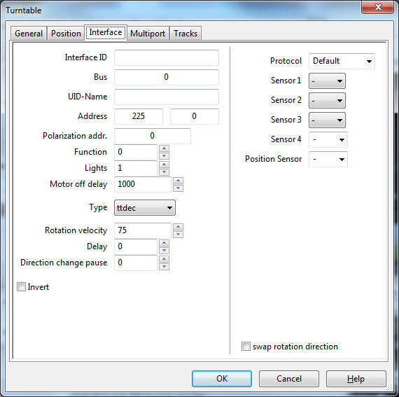
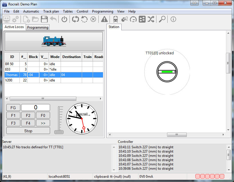
On the tab 'Tracks' we will add the possible entries to our turntable:
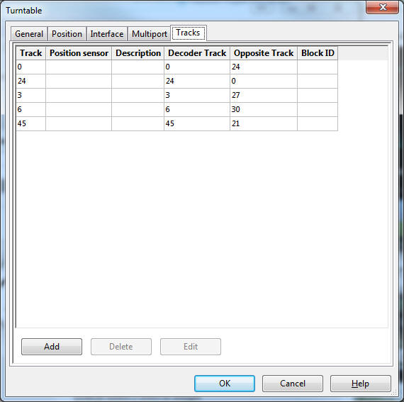
The Märklin Turntable 7286 with Digital-Decoder 7687 has a maximum of 48
positions (Tracks).
So the opposite track is therefore always + or - 24
After you click the "OK" button, our turntable did get some entries, onto wich
we can draw/connect some tracks: